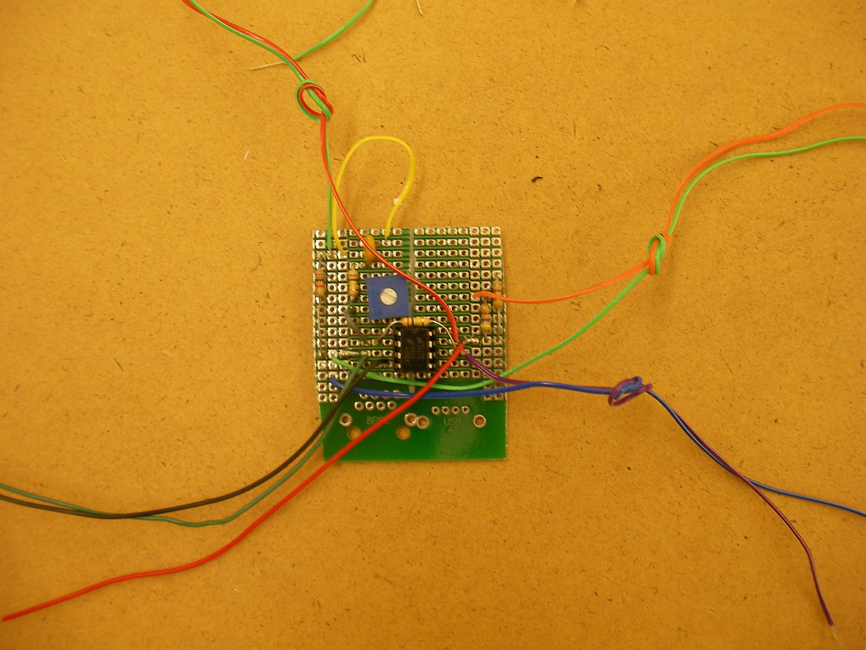
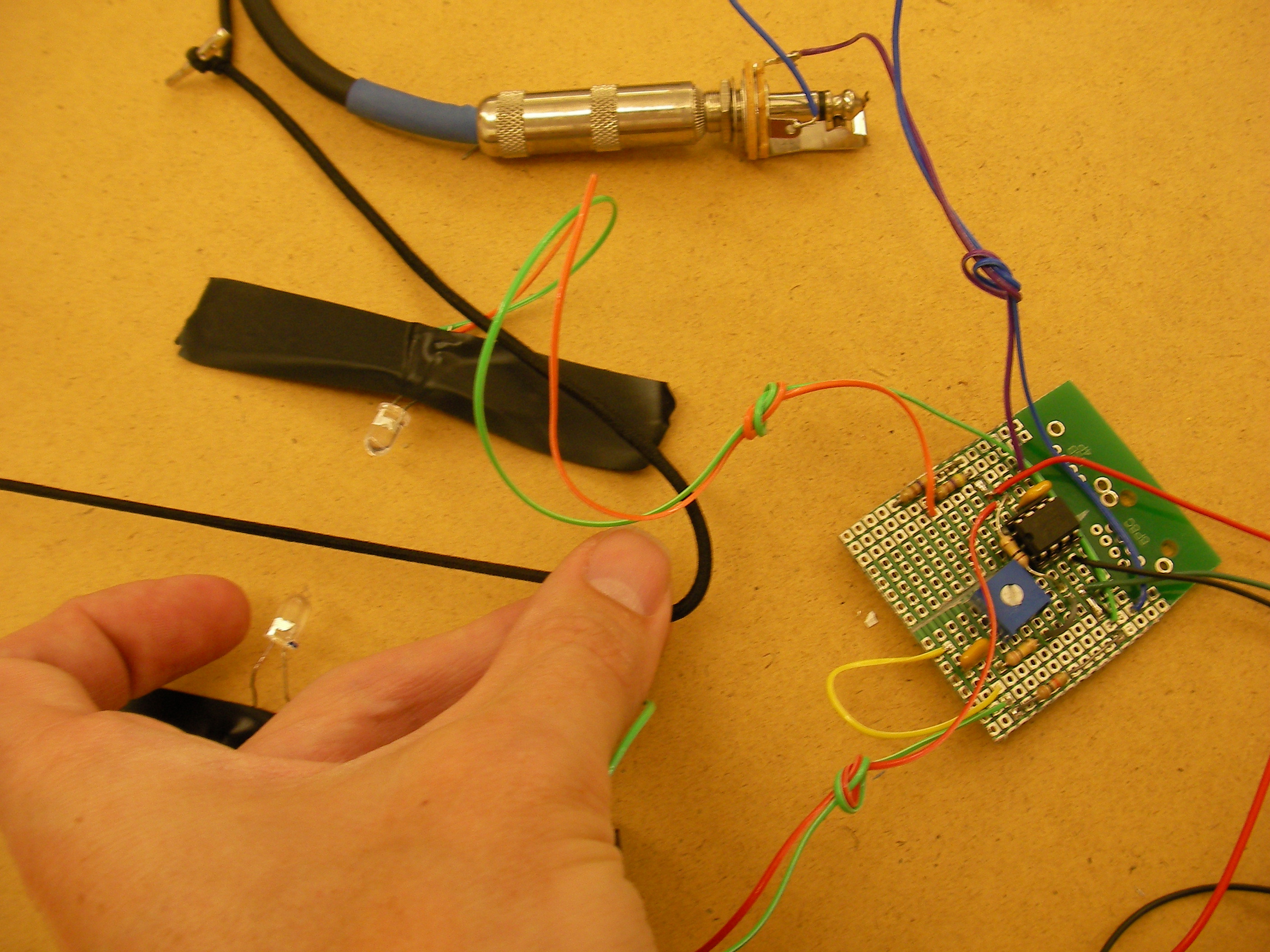
Plug this rubber-band bass into a standard guitar or bass amplifier, and you can play amazingly low frequencies and cool sounds. Each rubber band sits between a paired infrared LED and receiver, and as it vibrates, it varies the amount of light detected. Each string’s signal is then amplified and mixed with the signals from other strings.

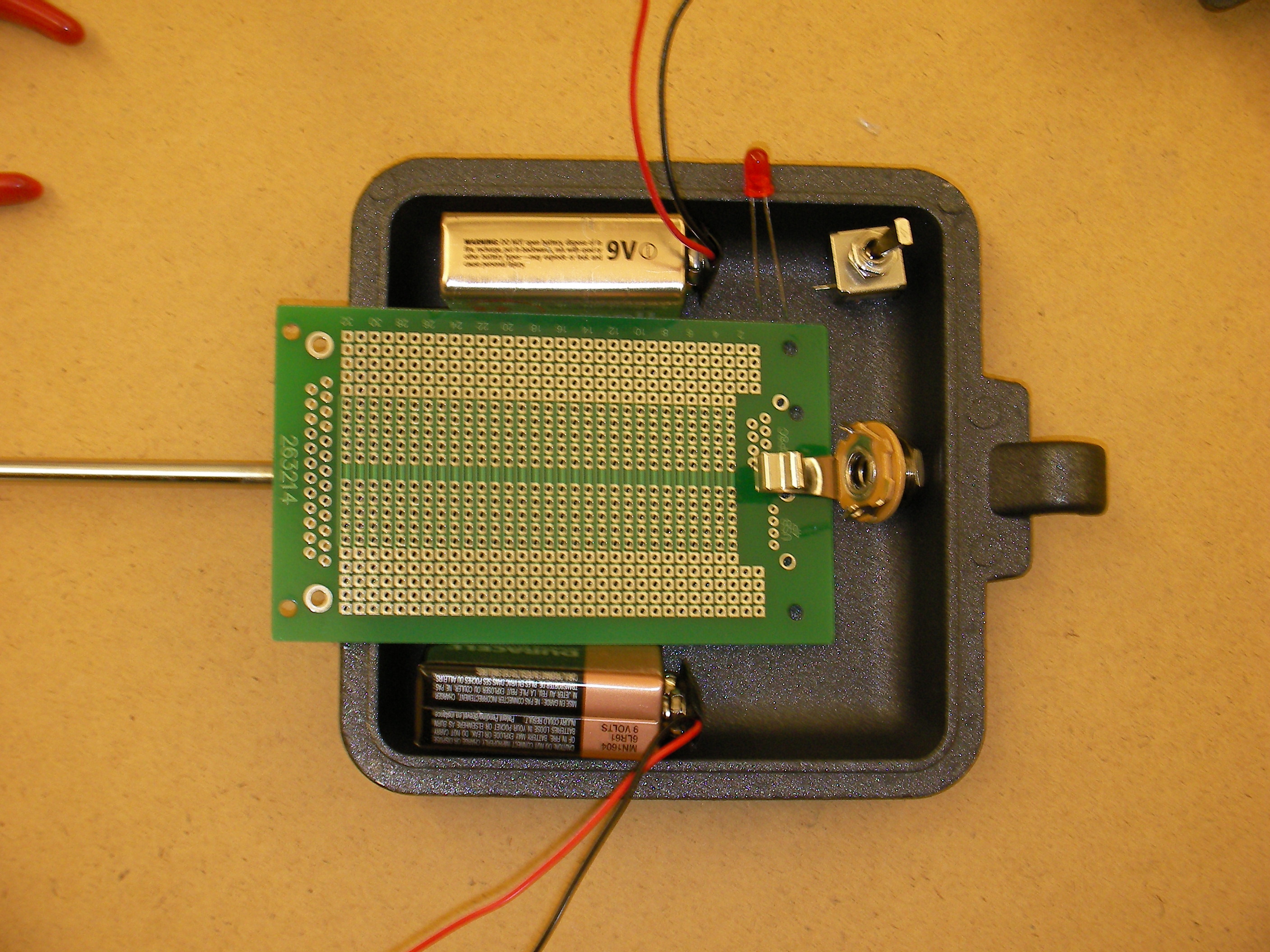
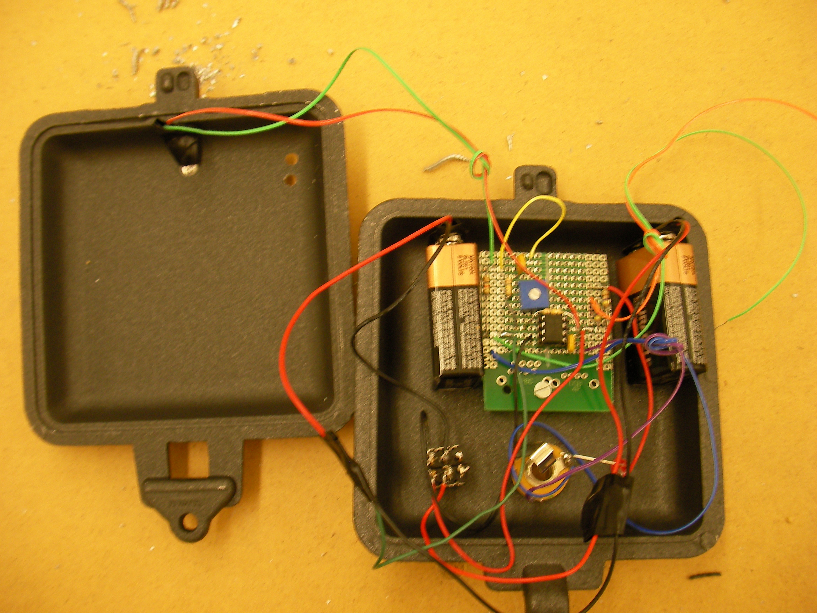
Rubber bands sound very different from steel or nylon strings. Their tone is rich in harmonics, and the high frequencies damp out fast. Rubber’s high elasticity also means you can generate unusually low notes out of short lengths of band. Because the amplifier requires both positive and negative voltages, I power the guitar using two 9V batteries, which are switched with a single dual-pole toggle. A red LED indicates when power is on. My original version had 4 elastic bands, one much longer than the rest. For simplicity, this article shows how to build a single-string version, which you can easily extend to accommodate multiple strings.

Project Steps

Plan the overall layout.

Figure out how you’ll fit the circuit board, components, and batteries into your guitar body. My sandwich maker’s interior measured 4″x4″x1 1/4 ”, so I had to trim the board a bit. I used a saw, but you can also score a line with a file or Dremel and snap the board along the line.

You have lots of options for the guitar body. You could use a toy guitar, a frying pan, anything that will hide the electronics and extend out to stretch the strings. For my original multi-string bass, I machined the body out of aluminum stock. Shape, size, and strength don’t matter much because string tension is low — a toy plastic ukulele will generate notes more typical of an upright bass!

If you’re building your own guitar body, leave extra room for wires and components; it’s easy to underestimate.

Build the circuitry.

The instrument’s mixing electronics are based on a classic op-amp summing amplifier circuit. An input capacitor for each string blocks DC voltages to make sure you’re amplifying only the vibrations (AC). Then potentiometers adjust each string’s output signal to less than about 0.5V, for uniformity. The adjusted outputs are added via a shared connection and then fed into an integrated circuit amplifier, a 741 op-amp, which boosts the combined signal. An output capacitor blocks any DC signals from entering your guitar amplifier.

Power for the op-amp comes from switched 9V batteries. The op-amp, capacitors, potentiometers, and resistors all connect on the circuit board itself, while the batteries, switch, LEDs, detector(s), and audio jack are outboard components.

Use solder and hookup wire to assemble the mixer/amplifier components on the circuit board, following the dowloadable schematics above under Files. (The schematics show the single-string instrument in black and optional strings in red.) Any layout will work, so long as the connections are correct; I centered the op-amp and put the capacitor-resistor-potentiometer input sequence along the left side of the board, and the output capacitor on the right.

The 2 battery snaps connect in series, with each end connecting back to the board through one side of a double-pole toggle switch and with a ground lead at 0V between the 2 batteries.

Recalling that IC pins are numbered counterclockwise from the dot or notch, connect the op-amp’s pins 4 and 7 to the –9V and +9V sides of the power, respectively. Pin 3 connects to the negative input (ground) and pin 2 connects to the positive (signal). The op-amp’s output, pin 6, connects through a capacitor to the tip of the  1/4″ audio jack, and the ring of the jack connects to ground. Solder more leads from the board to connect out to the power indicator LED, the infrared transmitter(s), and the phototransistor(s).

Test the circuitry.

It’s prudent to test the circuitry before assembling it onto the body. If you’re building a multi-string instrument, test 1 transmitter/receiver pair with a rubber band before forging ahead with rest. I spread the circuit out on a table and taped the transmitter and receiver down so they sat slightly above the surface and pointed directly toward each other about 1″ apart.

Plug in the batteries, stretch an elastic band between the emitter and receiver, and test for output from the jack using a voltmeter on an AC setting or an oscilloscope. The output should jump a few tenths of a volt when you pluck the band. If you see signal, you can hear it by plugging into headphones, an amp (begin with the power turned down), or a cheap set of powered computer speakers.

If you don’t hear an amplified tone from the string, try turning up your amp, but if you go past 5, something else is probably wrong. Check that you haven’t inadvertently swapped the transmitter and receiver, which look similar, or reversed the polarity of either. Test the detector by illuminating it with a bright incandescent source, such as a 60-watt bulb or old-fashioned flashlight, instead of the IR transmitter. Direct the light into the receiver, and pluck the rubber band close to and in front of the receiver.

If you still get no signal, test the voltage between the phototransistor’s emitter and ground, across the 1kΩ resistor. If the DC voltage there is zero, chances are the phototransistor is backward. The AC voltage at this point should also increase when you pluck the rubber band. If the detector generates signal at the 1kΩ resistor but the amplifier output still doesn’t work, double-check the connections and solder joints on the board.

Assemble the body.

Once the circuit is working, it’s time to mount the components onto the body. First comes some drilling. Conveniently, my Coleman Camp Cooker was made of soft metal and its 2 halves come apart easily, making it easy to work with. I put holes in the case for the power switch, power indicator LED, output jack, and a standoff that holds the circuit board away from the case, to prevent short circuits.

For the photodetector, I drilled another hole centered on the body, just below the guitar’s neck. At one of the neighboring corners I drilled 2 more holes for the emitter, one for the 1″ standoff and the other for the wires. Then I cut a short length of IC shipping tube to use as an arm that cantilevers the emitter over the detector.

I drilled 2 holes in the arm, one to attach to the standoff, and the other to mount the transmitter. Take care to position the holes such that the transmitter is directly above and aimed at the receiver. All of the LED-style components — the indicator light, emitter, and receiver — press-fit easily into holes drilled with a #9 (0.196″) bit.

Add the string, bridge, and tuning head.

I tied one end of the elastic band to the cooker’s hanging hole, opposite the handles. For the bridge, I used a piece of IC tubing with a notch in it to prevent the elastic from sliding from side to side.

To hold the other end of the elastic, I made a movable “tuning head” out of more tubing. I drilled 2 holes in the plastic for the cooker’s handles to pass through, and another hole higher up to tie the elastic to. This arrangement lets you easily slide the head back and forth to adjust the tension in the elastic, while the torque against the handle prevents the head from sliding on its own.

The guitar is ready to play! If you have multiple strings, the potentiometers let you even out the volumes (the signal level increases for very low notes), and otherwise protect your amp if the gain is high. The other thing to play with is the alignment of the emitter and detector. Rotating the emitter’s mounting arm may increase the signal level.

Play the fantastic elastic.

Due to the low tension, you can play incredibly low notes with just a short length of elastic. It also makes this instrument sensitive; depending on how you pluck or strike the strings, their tuning might change. Rather than play the elastic bass like a guitar, changing the notes by fretting against the neck, try tugging on the elastic at the neck, like with a washtub bass, or squeeze down on it behind the bridge.

You can also control the tone using your fingernail as a sliding fret, lifting the string just enough to give it a new vibrating length. Apply just slight pressure.

Notes also have a different character depending on whether you pluck them hard or soft, with the “hard” notes containing more high-frequency components. It’s easy to make a lot of cool sounds with this, but challenging to play a song. The best way I found to keep a consistent tone was to play the multiple-string instrument and gently hammer on its strings with chopsticks rather than pluck them.

Finally, remember these are optical pickups, so you can experiment with almost anything! Plucking the tines of a plastic comb held between the sensors produces a really creepy sound. Even tapping on the base of a wineglass can be amplified. For my next experimental instrument, I plan on optically amplifying the motion of glass rod.

Schematics plus videos and audio recordings: http://www.makezine.com/17/diymusic_elas…

Conclusion

This project originally appeared in MAKE Magazine Volume 17.

Related Posts on Make: Online:

How-To: Two-String Paddle Bass

http://blog.makezine.com/archive/2010/07...

Bass String Winding with Antique Machinery

http://blog.makezine.com/archive/2009/05...