WARNING: The circuits shown herein do not provide isolation from the AC mains, and therefore any part of the circuit can be exposed to dangerous voltages relative to earth ground. Extreme care must be observed in testing or handling these circuits while connected to the powerline.

AM486 appliance modules are essentially relays that are rated for 120V/15A and thus they are well suited to the task at hand. These relays are of a bi-stable design, meaning that they require no holding current to remain either open or closed but additional circuitry is required to determine their current state.

For this project one relay was allocated to each of the functions in the dishwasher which are:

  • pump motor
  • water fill
  • drain
  • soap dispenser #1
  • soap dispenser #2
  • blower motor

What will the next generation of Make: look like? We’re inviting you to shape the future by investing in Make:. By becoming an investor, you help decide what’s next. The future of Make: is in your hands. Learn More.

Project Steps

The first step consisted in performing a reverse-engineering analysis of the circuitry used on the AM486 modules.

The PCB uses a single copper layer which makes it very easy to trace the circuit. My analysis was confined to these areas: Power supply; Relay control; Relay state sensing.

The attached schematic shows the diagram for each area. Upper-left corner: relay state sensing; Upper-right corner: power supply; Middle: relay control; Bottom: dishwasher function.

For the next phase of the analysis I removed all of the unnecessary components from the PCB and attached an Arduino Pro Mini board by connecting:

The RAW and +5V signals to the corresponding power signals of the Arduino board,

The CONTROL signal to one of the digital outputs,

The SENSE signal to one of the analog inputs.

To aid in the development, I also connected a BluetoothMate module to the Arduino board. This way I could send commands and debugging data to and from my development PC.

CAUTION: Since the circuits that we are dealing with here are not isolated from the AC mains, it would likely be very unwise to attempt to make a wired connection from the Arduino board to a PC’s serial port.

I soon found out that the current draw from the Arduino+Bluetooth was overloading the transformerless power supply of the AM486 module. However, simply increasing the value of C3 and choosing components for D2 and R8 with a suitably higher power dissipation rating solved the issue.

Through experimentation I determined that the relay can be reliably actuated by sending 4 1-ms pulses evenly spaced over one powerline AC cycle.

The analog values read from the sensing circuit were like this:

0V if the relay switch is open and the load is disconnected;

Toggling between 0 and 5V (in sync with the AC) if the relay switch is open but the load is connected;

5V if the relay switch is closed regardless of whether the load is connected or not. Thus the final scheme adopted for sensing the state of the relay was to sample the analog input for about 2 powerline AC cycles and return the average value.

The final revision of the Arduino sketch used for analyzing the relay circuit behavior is in the “dishwasher1.pdf” attachment.

Once the circuits and basic control software have been identified, what remains is to harvest the necessary components from the AM486 modules, assemble them onto the project’s circuit board, and write the Arduino sketch that controls the timing of the relays to emulate the operation of the electromechanical timer.

Clearly, because there are multiple functions to control in the dishwasher, the relay control and state sensing circuits have to be replicated that many times with each CONTROL or SENSE signal connected to a corresponding digital or analog pin on the Arduino board.

Luckily, the Arduino Pro Mini board is provisioned with enough digital and analog pins that one doesn’t need to come up with any sharing schemes (such as using multiplexers).

The Arduino sketch used to control the dishwasher timer is contained in the attachment “dishwasher2.pdf”

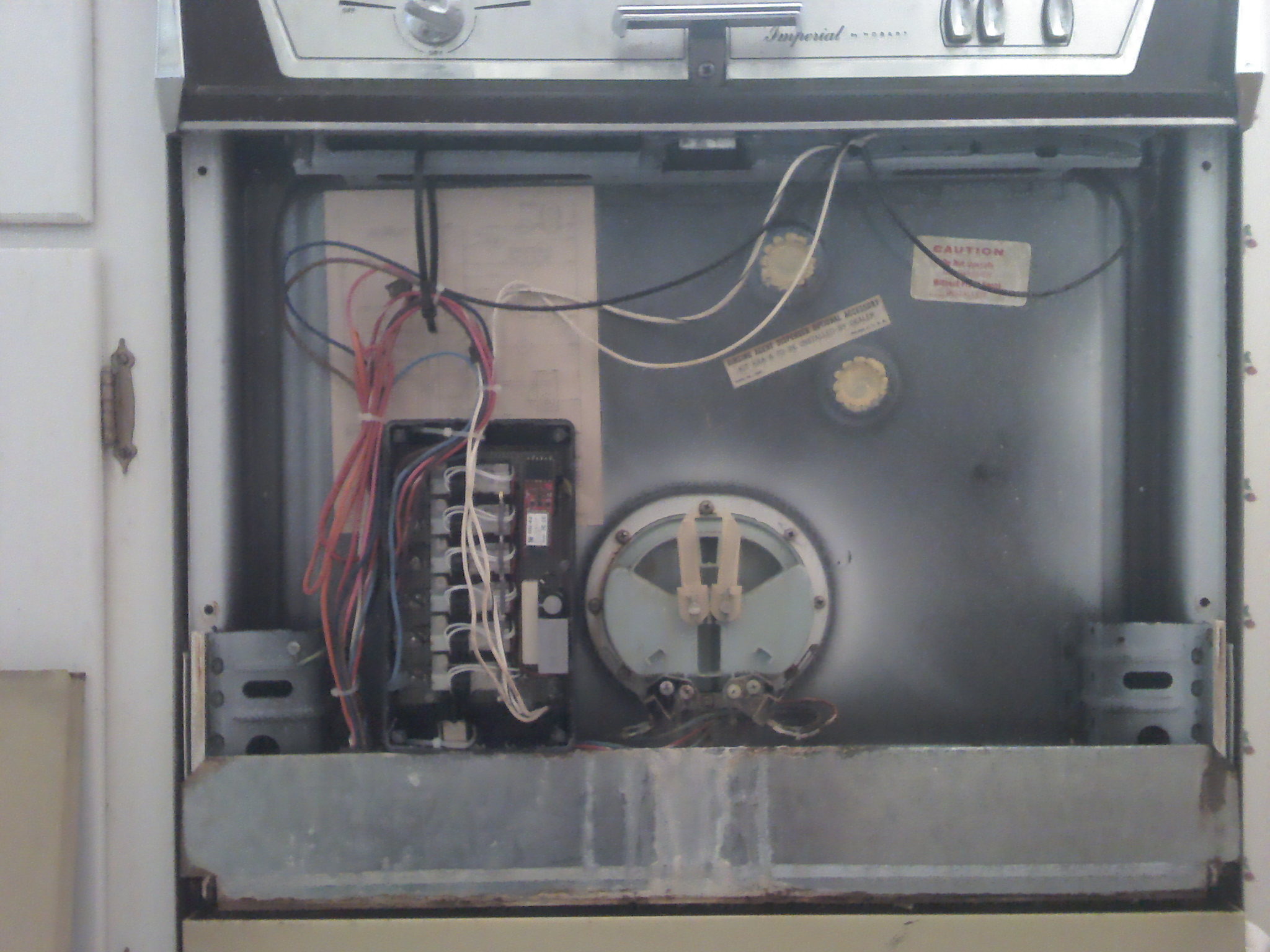
Attachment of the electronic timer assembly to the dishwasher was straightforward: it fit nicely behind the front cover and the function wires along with the AC live and neutral were moved directly from the electromechanical timer to the terminals provided on the circuit board.