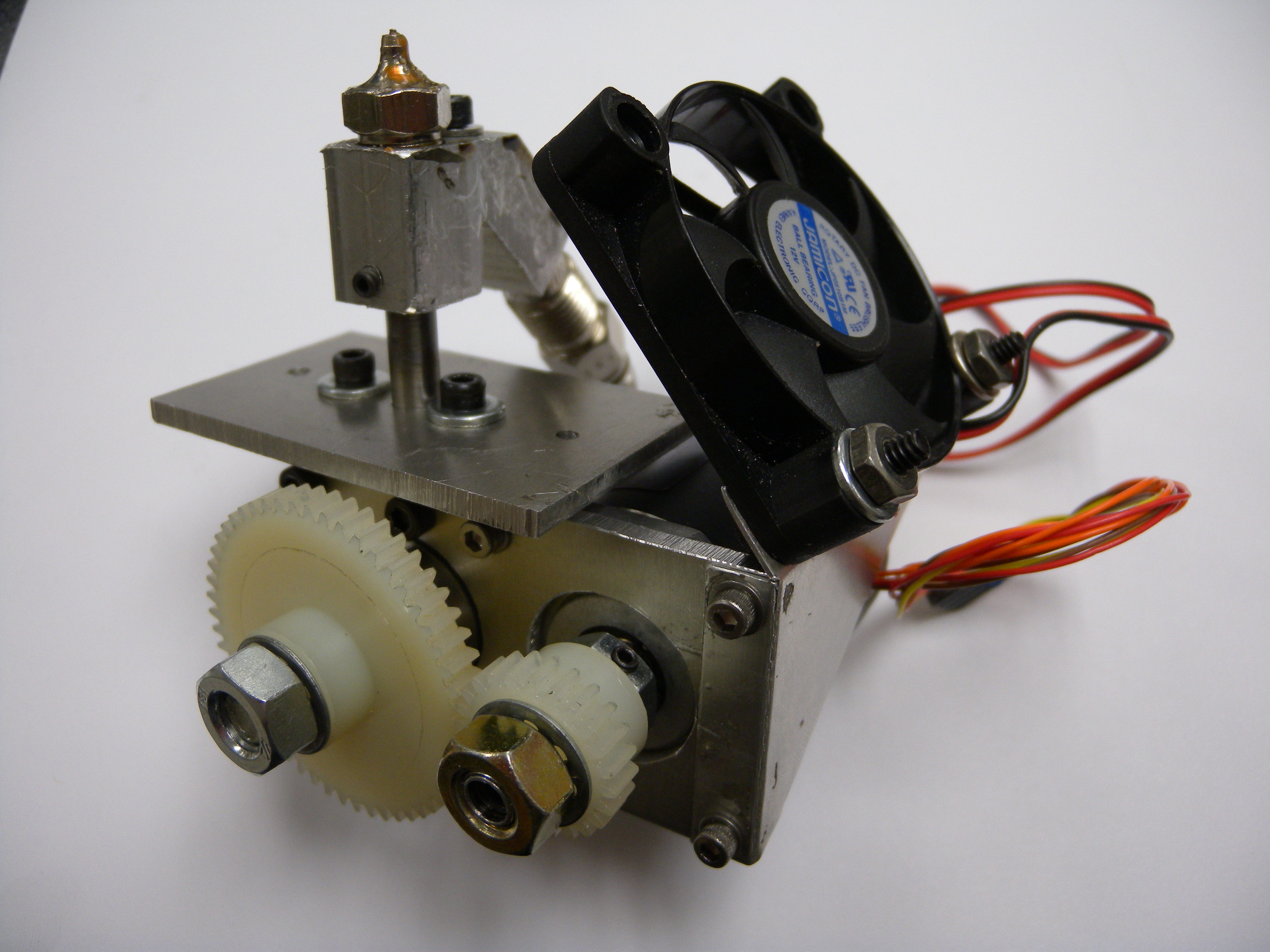
I love 3D printing, so I decided to build my own printer. After playing around with commercial machines like MakerBot’s Cupcake and Thing-O-Matic, it hit me that I could make my own printer and 3D printer extruder for free, or very near it.

So, off I headed down the long and winding road to design and build a small 3D printer (or as my son likes to call it, the Toy Machine). After a great deal of dumpster diving, I scavenged enough stepper motors, linear rails, and drive belts for the mechanical parts, but I was stumped when it came to the heart of the printer: the 3D printer extruder. The internet turned up a slew of fancy designs, but all possessed one design flaw: they required 3D printed parts, so you’d need to have a 3D printer to make a 3D printer!

My solution was to build this robust extruder using a handful of tools, one online parts order, and a trip to the auto-parts store. For a heater, it uses a $10 glow plug from a diesel engine, and it performs as well as commercially available extruders.

What will the next generation of Make: look like? We’re inviting you to shape the future by investing in Make:. By becoming an investor, you help decide what’s next. The future of Make: is in your hands. Learn More.

Project Steps

Apply templates.

Download, print, and cut out the templates for the body block, heater block, base plate, motor mount, and bearing mount from thingiverse.com/thing:153464. Test-fit them over the appropriate aluminum stock, positioning them to use as much original edge as possible; this will save you some cutting and give you a straight reference point.

Make sure to align the base edge of the body block along the bar’s original edge. This will help keep the body perpendicular to the base plate.

Remove the templates and lightly spray one side of the aluminum with spray adhesive. Carefully align, then stick the templates onto the aluminum.

Cut the aluminum parts.

Secure the stock in a vise and carefully cut out the parts with a hacksaw, or a bandsaw with a metal blade. Take your time and constantly check your work to make sure your cuts are perpendicular to the face of the stock, because in future steps you’ll rely on these edges for reference and drilling.

NOTE: For the 1/8″ aluminum parts, it’s easiest to cut the bar to width first, then drill holes, and finally cut the 3 parts free.

Drill the aluminum parts.

Use a center punch to mark the centers of each hole on the templates. Following the template reference drawing, locate the remaining holes with a permanent marker and mark them with the center punch.

Secure the body block in the drill press’s table vise, align the vise, and clamp it in place. Add a small amount of cutting oil and drill the hole. Repeat this process for all remaining holes in each block, using the appropriate drill bits. For the ½” hole (radius 0.250″) and 22mm holes, pre-drill with a ¼” drill, then drill the larger, final hole. This will reduce the wear on the larger bit and prevent it from jamming.

For the 2 countersunk holes, measure the depth directly onto the drill bit using a caliper and mark the depth with a piece of masking tape. After you drill the thermocouple mounting hole, located next to the nozzle, make a shallow groove that crosses over the hole with your hacksaw. This will help keep the thermocouple from “walking” when you tighten it down.

Tap the holes.

Tap each of the threaded holes (marked in yellow on the template drawing) using the appropriate tap. Use a liberal amount of cutting oil and work slowly.

TAP TIPS: Secure the tap in the handle, center it in the hole, make one full turn while applying gentle pressure, then back off the tap until the threads “click.” Now make ¼ to ½ turn, then back the tap until the threads “click” again; repeat this process until the hole is completely threaded.

If the tap is binding, or it feels unusually hard to tap, back the tap out and try again. Make sure you’re holding the tap as parallel with the walls of the hole as possible.

Set up your drill press to hob a bolt.

Traditionally the extruder’s feed wheel is a hobbed bolt that’s made using a lathe and a specialty jig. But you can just as easily hob a bolt (that is, cut gear teeth in it) using a drill press, a tap, a couple of washers and nuts, and 2 skateboard bearings.

Using your caliper, measure and mark the unthreaded portion of the bolt, 13.35mm away from the base of the head. (This will locate the hobbed section directly in line with the filament and nozzle when the extruder is assembled.)

Clamp 2 skateboard bearings in your drill press vise as shown. Slide the bolt through the bearings and secure it with a washer followed by 2 nuts. Tighten the first nut, then hold it in place while you tighten the second nut, making sure the bolt still spins freely. This second “jam nut” will keep the first from loosening as the bolt rotates.

Gently secure the M4 tap in the chuck, upside down, and make sure it doesn’t wobble as it spins. Lower the press and align the vise so that the mark on the bolt just touches the tap. Secure the vise in place, raise the press, and flip the tap around in the chuck. This alignment procedure will help prevent you from over-cutting the teeth into the bolt.

Cut the feed wheel.

Liberally oil the tap and bolt and turn on the press. Slowly lower the press until the tap just makes contact with the bolt and begins cutting.

Continue to lower very slowly. The tap should grab enough of the bolt so that it spins with respect to the tap. Continue lowering the press until the peaks of the cut teeth just meet. Retract the press and check your work. Be as careful as possible during this procedure to not break your tap or produce uneven teeth.

Once the teeth are cut, measure the diameter of the hobbed section. You’ll need this for your feed rate calculation later.

Cut down the nozzle.

One of the biggest hurdles I faced with this design was finding an inexpensive and easily sourced solution for the nozzle. Eventually I stumbled upon a brass dispenser that uses a 22-gauge stainless steel needle. Perfect! Isn’t it nice not having to drill a 0.4mm hole? I think so.

Secure the dispenser in your vise and carefully cut off all but 1mm of the needle using a fine-toothed file or a rotary tool with cut-off wheel. Gently polish the exposed needle using 400-grit sandpaper and, if needed, a razor blade to deburr the hole.

TIP: Some dispenser needles may be partially blocked, which isn’t a problem for fluids but is for molten plastic. Clear the dispenser using a 1/64″ bit and the remaining needle as a guide.

Drill and tap the nozzle.

Align and secure the nozzle in the vise so that the hole in the back of the nozzle is parallel with the press. Set the depth of the #3 drill bit to 0.275″ using your caliper and a piece of tape, and secure the bit into the chuck. Add cutting oil to the nozzle and carefully drill the hole.

With the nozzle still in the vise, remove the drill bit and replace it with the 1/4″-28 tap. Use the press to start the tapping process, as it is properly aligned with the hole. Remove the tap from the chuck while it is still inside the nozzle and complete the tapping process by hand.

Bore the heater barrel.

Cut a 2″ length of ¼” stainless rod using your hacksaw and smooth the cut end with a file. Secure ½” of the rod in the drill press’s chuck, lower the press, and secure the exposed rod in the vise. While the press is still lowered, clamp the vise to the drill press table. Un-chuck the rod and it should now be properly aligned with the press.

Insert the center drill into the drill press and mark the center of the rod. Remove the center drill and replace it with the 4mm bit. Add a liberal amount of cutting oil to the end of the rod and begin drilling out its center. After you have drilled about ¼” of depth, retract the drill, add oil, and start again. Repeat this process until the center is completely bored.

Thread and install the heater barrel.

While the heater barrel is still clamped in the vise, thread 0.375″ of the end of the rod using the appropriate thread cutting die and a liberal amount of oil. After cutting, clean up the all the oil and remove any burrs from the threads and the hole.

Firmly screw the nozzle onto the end of the heater barrel. You can use a bit of high-temperature thread compound to cope with leaks, although I don’t use any on mine and have been leak free.

Make the motor couplers.

Secure the center drill in the chuck and lower the press. Secure the center drill in the vise and loosen the chuck. Slide the 5/16″×1″ bolt into the chuck, head down. Turn on and slowly lower the press until the center drill marks the head of the bolt. Remove the bolt and center drill from their clamps and place the bolt in the vise. Place the 5mm drill bit in the chuck, align the bolt, and drill out its center.

Repeat this process for the remaining bolt using the appropriate drill bit that matches your stepper motor’s shaft diameter.

Lay the bolt on its side and secure it in the vise. Use the center punch to mark the center of one of the bolt head’s faces, and drill it with the #36 bit. Select the #6-32 tap and thread the hole. Insert a setscrew into the hole and the coupler is complete. Repeat for the other coupler.

Make the fan mount.

Use spray adhesive to attach the fan mount template to the aluminum sheet and carefully cut around the outline. Drilling holes in sheet aluminum can be a bit tricky and dangerous, so make sure the mount is secured tightly when drilling and use a piece of wood underneath to prevent burrs.

Secure the short side of the flat fan mount in the vise so that the jaws of the vise are lined up with the bend line. Carefully bend the mount 90° using a piece of wood or hammer.

Bend the other side, in the same direction, approximately 25°.

Prepare the gears.

Bore the 52T gear with the 8mm drill and the 24T gear with the 5/16″. This will allow them to slide easily over the bolt couplers.

Clamp one of the 8mm nuts in the vise and mark the center of one of the faces with your center punch. Secure the #32 bit in the chuck and center the nut with the bit. Clamp the vise in place, add cutting oil and drill the hole completely through the face, but not through the entire nut.

Tap the hole using the #6-32 tap and cutting oil.

Assemble the hot end.

To complete the hot end assembly, slide the heater barrel into the heater block and tighten the nozzle using the adjustable wrench. Make sure it’s quite tight, as you don’t want molten plastic weeping out of the threads.

Slide the glow plug into the heater block and secure it with a setscrew. Slide a length of PTFE tubing into the heater barrel until it stops against the nozzle. You want the PTFE to be long enough to fit into the barrel and make a good seal. Trim off the excess tubing and leave about 1mm exposed.

Assemble the extruder.

Attach the body block to the base plate using 2 washers and #4-40 screws. If your alignment is off, you can compensate by drilling out the holes in the base plate with a slightly larger bit or widen the hole with a jeweler’s file.

Slide the heater barrel through the base plate and into the body and secure in place with a setscrew.

Assemble the extruder, cont'd.

Attach the bearing mount and motor mount onto the body block using 4 washers and #4-40 screws on each side. Slide the two 608 bearings into their holders and pass the hobbed bolt through the bearing on the backside of the block and through the bearing on the front. Thread the lock nut over the threaded end and lightly tighten it against the bearing. The hobbed bolt should rotate smoothly. Once the lock nut is properly positioned, fix it in place by tightening the setscrew.

Place the large feed gear over the threaded end of the hobbed bolt and secure in place with a lock washer followed by a 8mm nut. Attach the stepper motor to the motor mount using 4 washers and screws. (If you find that the stepper is too wide, you can lightly shave down one side of the 608 bearing with a rotary tool or belt sander; just don’t remove too much material.)

Slide the coupler bolt over the motor shaft and secure it with the setscrew. Slide the drive gear over the coupler and secure it with a lock washer and nut. Make sure the gears mesh nicely. If they’re too loose or too tight, make adjustments to the motor mounting position at the motor using a file.

Assemble the extruder, cont'd.

Mount the cooling fan to the bottom of the base plate using two #6-32×¾” screws and attach the fan so that it blows across the exposed heater barrel.

Strip ⅛” off the ends of the heater power wires and crimp a ring terminal to each. Secure the positive lead to the end of the glow plug and the negative to the extruder body.

Screw the ¼-20 nylon tensioner into the body and lightly tighten it. Attach the thermocouple to the bottom of the heater block and your assembly is complete.

Conclusion

You did it! Wasn’t that easy? You now have a super-robust homemade extruder ready to start pumping out plastic for your next project.

But wait! Don’t get ahead of yourself. Rather than throw the extruder straight into your printer, hook it up to a bench power supply and a stand-alone temperature controller and see how it works. I like to play around with scrap filament and use a manually fed stepper controller to test my feed rates and flow rates. This will allow you to tweak alignments, adjust the tensioner, and make sure everything runs smoothly.

The first step to configuring your extruder is to locate the type of control electronics you’ll be using (RAMPS, GRBL Shield, or what have you). If you’re swapping an old extruder out of an existing printer, you might want to consider using that printer’s thermocouple and stepper controller. This will save a lot of the headache of reconfiguring the machine.

If you’re building your own machine, the connections are simple. Connect the temperature sensor, stepper, and motor to your controller and hook the glow plug up to the heater circuit.

CAUTION: You’re using an automotive glow plug that can reach dangerously high temperatures. Make sure you have implemented some order of thermal/circuit protection in order to prevent unintended fire or harm!

Now, for configuring your software. Determining the exact steps/mm at which plastic exits the nozzle requires some pretty heavy math and analysis. Rather than diving too heavy into the books, you can use the following calculation to get you into the ballpark and tweak the numbers as you print test pieces:

steps/mm = R * r / (