Seronik - Scorpius-c-f

Modern digital SLR cameras have made nighttime photography tremendously popular. Star-filled landscape photos and glorious images of the Milky Way and distant galaxies are now within the reach of aspiring astrophotographers. Combining previously unheard-of sensitivity with game-changing image quality, these technological marvels can turn night into day. But what a DSLR can’t do is stop the Earth from turning.

Seronik - DSC_4165

Put your camera on a regular tripod, and in just a few seconds of exposure, the stars begin to transform from intense points of light into elongated streaks. The longer the exposure, or the greater the focal length of your camera’s lens, the more pronounced the effect becomes. Blame it on the turning Earth. The same motion that makes the Sun appear to rise in the east and set in the west also carries the stars across the sky. The only way around it is to move your camera in the opposite direction at the same speed — one rotation per day. In a nutshell, that’s what this nifty tracking platform does.

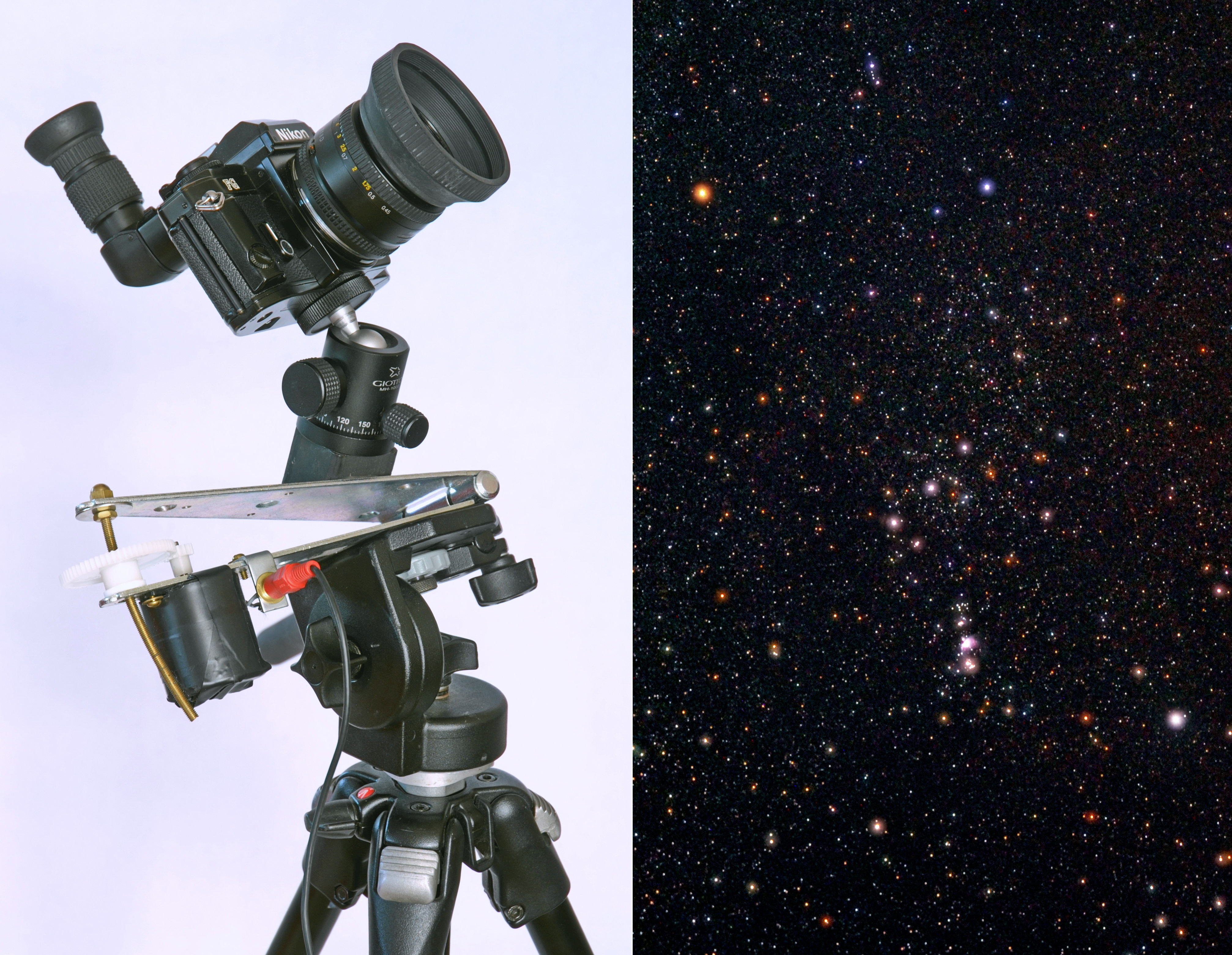
The Hinge Tracker accomplishes this trick the simplest way possible. A basic regulator circuit powers a DC gear-head motor, which turns a pair of gears that engage a curved length of threaded rod, and makes the hinge open at the correct speed. You can build it in a weekend about $75 or less.

Project Steps

Wire up the electronics

You can use a prototype board to make things tidy if you wish, but there are so few parts that I simply soldered them to each other as indicated in the schematic diagram here. Make sure you tape up (or heat-shrink) any bare wires to prevent short circuits.

Solder the 2-conductor cable to the RCA plug and connect it to your circuit where the schematic indicates the DC motor. This lets you easily unplug the electronics. (You’ll connect the motor and RCA socket later, in Step 7.)

NOTE: Don’t substitute a regular 500-ohm pot for the one specified. You do need the precision of a multiturn pot.

Assemble the project box

The regulator circuit is housed in a plastic project box. You’ll need to drill 3 holes in it: one for the power switch, another for the wire that connects the electronics to the motor via a standard RCA jack, and a third hole to access the potentiometer adjustment.

Carefully position the pot so that its adjustment screw (indicated in the second photo here) is accessible through the hole you drilled, and glue the part in place with 5-minute epoxy. Take care to ensure no glue ends up on the screw itself.

Bend the curved rod

For the mount to track accurately, the drive rod needs to be curved into a segment of a circle with a radius of 7″. Because it’s difficult to evenly bend a short length of threaded rod, start with a piece that’s at least 12″ long.

Use a compass to draw the required circle on a piece of paper taped to a flat surface. Next, place the threaded rod onto the paper and gradually bend it until the curve in the rod matches the one drawn on the paper.

Finally, use a hacksaw to cut out a 4″–5″ section from the rod. A segment of this length will yield around 1½ hours of uninterrupted tracking.

Modify the hinge

You’ll need to drill a few holes in the lower half of the hinge. Begin with the most important one — a 3/8″ hole for the motor shaft. Position it 1¼” from the center of the hole that the curved rod passes through (the one nearest to the tapered end of the hinge). Then drill and tap a pair of holes for mounting the motor.

In use, the Hinge Tracker sits on a standard photographic tripod, so you need to drill and tap a ¼-20 hole centered roughly 1¼” from the hinge-pin edge.

Lastly, drill and tap a hole to accommodate the right-angle bracket that holds the RCA socket.

Make the ball-head mount

Cut a 4″ length from a piece of 1½” hardwood stock, then bisect it at a 45° angle. (One piece becomes the mounting block, the other is scrap.) You can paint the block or leave it unfinished.

Screw a ¼-20 hanger bolt into the flat, top end of the block, then use J-B Weld adhesive to glue the angled end to the top half of the hinge, centered roughly 2½” from the pin edge, as shown here.

Prepare the main gear

A key part of the drive assembly is a nut that couples the large gear to the threaded rod. I used a blind well nut for this purpose. Prepare the gear by inserting the blind well nut and trimming off its rubber flange. You may need to enlarge the hole in the gear slightly with a round file for a good, tight friction fit.

NOTE: A regular 10-32 nut glued to the underside of the gear with 2-part epoxy should work nearly as well. If you choose to go this route, make sure that the nut is accurately centered over the hole.

Wire the motor to the RCA socket

Note that the positive and negative leads of the motor have to be reversed to ensure it runs counterclockwise — the correct direction for a tracker in the Northern Hemisphere. (Photographers in the Southern Hemisphere users will want the motor to run clockwise.) If the motor runs the wrong way, the tracking platform is literally worse than useless!

Attach the socket to the angle bracket and mount on the hinge.

Final assembly

Mount the motor on the hinge and fit it with the small gear.

Attach the threaded rod segment to the last hole on the top half of the hinge using a pair of nuts and washers as shown here. I used a brass acorn nut on top for a tidy appearance. The threaded rod should pass through the corresponding hole on the bottom half of the hinge without binding.

Next thread on the large gear. When the hinge is closed, it should mesh with the motor gear. (I added a teflon washer beneath the large gear, to better align my gears; your alignment may vary.) Your hinge tracker is complete.

Adjust the motor speed

Before attempting your first photograph you have to adjust the motor speed so that the large gear turns at exactly 1 rpm. The easiest way to do this is to mark one of the gear’s teeth with a felt pen, and add a small tick mark to the base. Run the motor, and start your stopwatch just as the marked tooth aligns with the tick. After exactly 2 minutes, stop the motor and see where the marked tooth is relative to the index mark. (For increased accuracy, let the motor run up to 5 minutes.) Adjust the multiturn potentiometer to speed up or slow down the motor accordingly, and repeat the test until the gear is turning at the correct speed.

Align your tracker with Polaris

To take star photos you first have to align the Hinge Tracker with the north celestial pole. For wide-angle shots, simply sighting along the hinge to aim at Polaris, the North Star, is good enough.

However, if you want better accuracy for longer focal length lenses or exposures more than 1–2 minutes long, you’ll need to be more precise:
• Set up your mount with the hinge pin on your left when you’re facing north, and use your tripod’s pan/tilt adjustment to aim the hinge pin at Polaris.
• Center Polaris in the camera’s viewfinder by adjusting the ball head.
• Swing the camera through 180° by lifting the top half of the hinge and observe the arc that the stars traces in the camera viewfinder.
• Use the ball head to tweak the camera’s position until it’s pointed at the center of the semicircle that the stars made in the viewfinder. This step aligns the center of the viewfinder with the rotational axis of the hinge.
• Now adjust the tripod so the camera is centered on Polaris, and repeat Steps 2–4 until the star doesn’t appear to move when you perform Step 3.

The entire process takes only a minute once you’ve done it a couple of times.

Now take some astrophotos

With the tracker is polar-aligned, you’re ready to take photos. Turn on the motor and aim your camera by adjusting the ball head only. (Move the tripod head and you’ll lose your hard won polar alignment!) Set your camera’s lens to infinity focus and a stop or two down from wide open for best performance. Begin with ISO 800 or greater, and try a 1-minute exposure to see what you get. Experimentation will guide you to the optimal settings.

Several accessories will make your life much easier. First, a remote control shutter release (preferably with an interval timer) is a real help. Second, if your camera doesn’t have a tilting viewscreen, a right-angle viewer that attaches to your camera’s optical viewfinder saves a lot of neck strain.

In practice you’ll rarely have to take exposures longer than 2 or 3 minutes duration — and often less than that. You can achieve the equivalent of longer exposures by taking several short ones, and adding the resulting frames together with software, such as the freeware program DeepSky Stacker. I have used lenses with focal lengths as long as 135mm (which functions as a 200mm lens on my Nikon DSLR) and achieved fine results. But start off with short exposures and a wide-angle lens until you work all the bugs out of your tracker and get the hang of shooting at night.

Conclusion

The Hinge Tracker won't replace a heavy-duty commercial tracking mount, but for a quick and easy entry into astrophotography, it can't be beat. You can certainly make a more complex tracker and hew toward the "super dorky" end of the range with stepper motors, but I prefer to aim for function with the greatest simplicity. The Hinge Tracker reflects that approach. And hey, I'm really just an analog kind of guy.