YouTube player

In this project, we will combine an Arduino, a Ping sensor, and a small assortment of components, to build a project that senses distances as “hot/cold.” Once built, we’ll walk through the software running our basic “sketch,” (what an Arduino program is called) and then experiment with variations of the “hot/cold” theme, all the while using the same circuit.

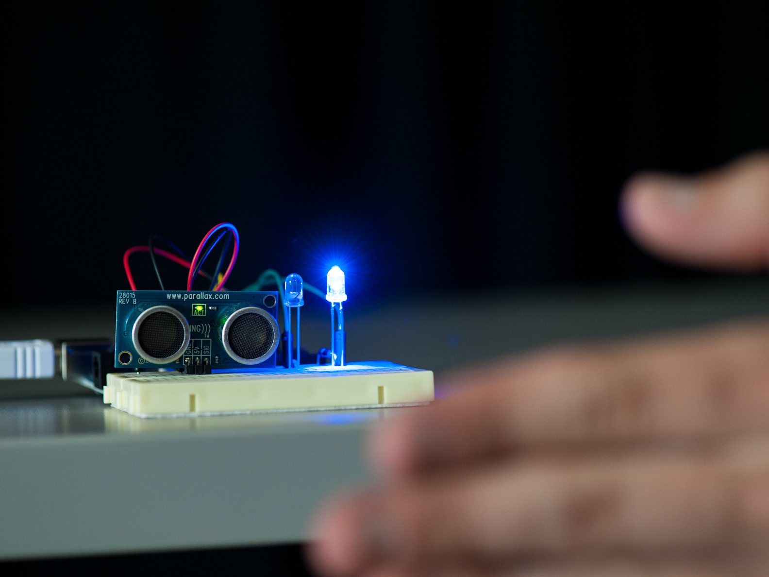
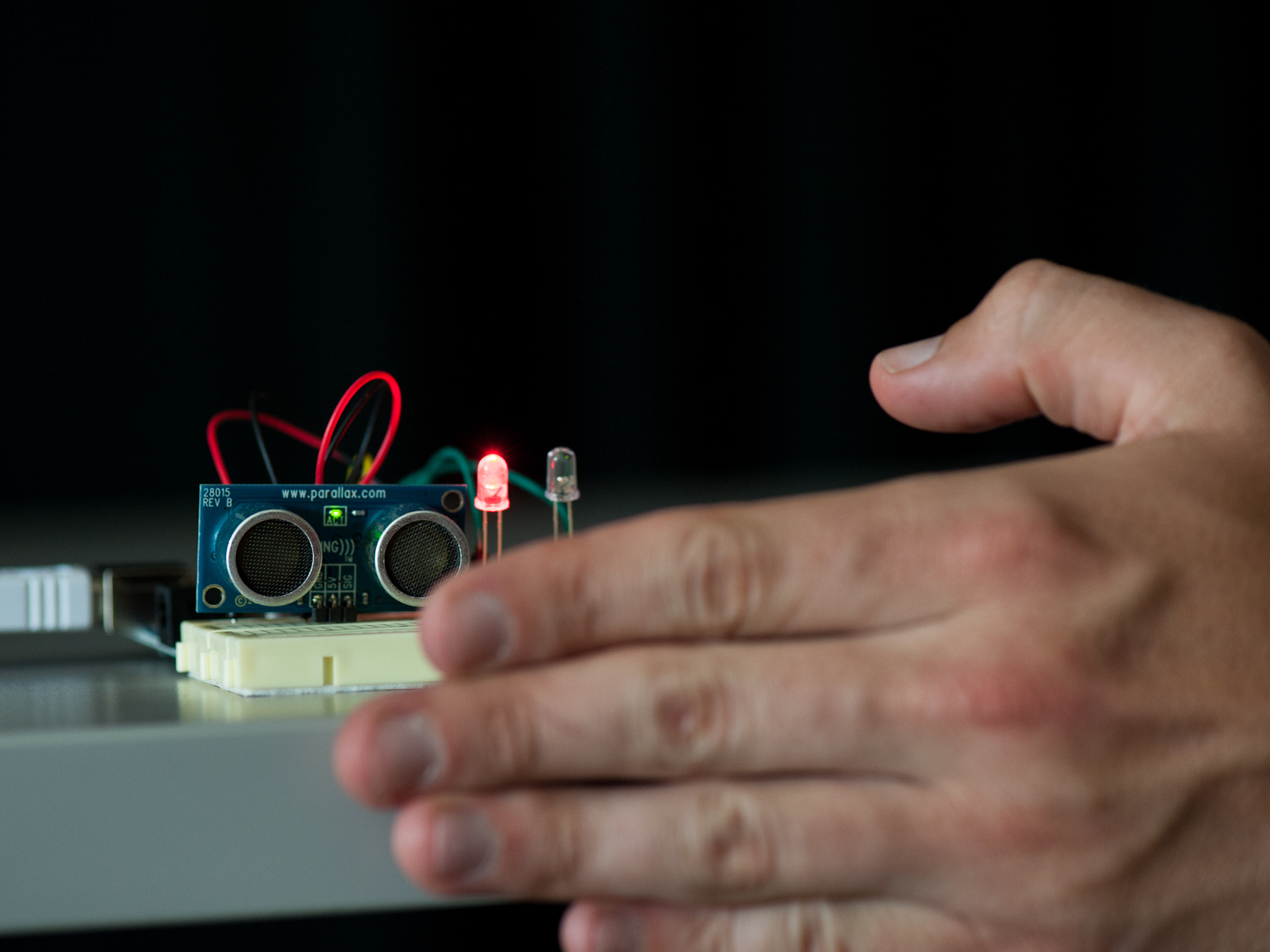
For the Arduino sketch files provided, the V1 sketch is detailed below. It measures distance from the sensor. The farther you are from the sensor, the “cold” blue LED begins to glow, and then the closer you get to the sensor, the “cold” LED fades away and the “hot” red LED turns up to full brightness!

The V2 sketch is a “capture the ping” game. At first, the “cold” blue LED glows, and every so often, the “hot” red LED will flash. When the red LED is on, try to move your hand in front of the sensor quickly. If you are fast enough, the red LED will flash; if you are too slow (or cheat!), the blue LED will flash.

And finally, the V3 sketch is a simple “hot/cold” switch. When no object is present in front of the sensor, the “cold” blue LED will produce a slow pulse. When it does sense an object, say when you sit down in front of your computer, the “cold” blue LED will turn off and the “hot” red one will shine at full brightness. This switch can be used to trigger other effects, such as waking your computer up from sleep mode.

Project Steps

Gather all your components.

Believe it or not, these are all the parts you will require for this build!

NOTE: Resistors listed in subsequent steps are for the LEDs suggested in the parts list. If you want to use different LEDs, you’ll have to calculate the resistor required using Ohm’s Law. Search online for “LED calculator” to determine the resistor needed. The 500-pack of resistors is recommended so you always have a range of options available.

First, connect the breadboard to the Arduino. Using two jumper wires: connect one wire from the 5V pin on the Arduino to the power rail on the breadboard. Have the other go from the GND pin to the ground rail.

Take a look at the Ping sensor. You‘ll notice three pins next to each other, labeled GND, 5V, and Sig (as in “Signal”). Now, let’s wire up the connections necessary to supply power, ground, and signal to the Ping Sensor.

Decide where you want your Ping sensor located on the breadboard. Make a connection between the ground rail and the sensor’s GND pin row. Add another wire between the power rail and the sensor’s 5V pin row. Alternatively, you could use short pieces of 20 AWG hookup wire.

Lastly, make a connection between the Ping sensor’s Sig(nal) pin row, and the Arduino pin labeled number 7. This connection will work in two directions: It will be used to send the “ping“ from the sensor, and also transmit the signal coming back from an object in front of the sensor.

Place the Ping sensor.

Place the Ping sensor on the board so that the connections line up with the wires you just placed. Carefully check to ensure all the connections are correct. Trace the connection from the Arduino GND pin to the ground rail, to the GND pin on the Ping sensor. Do the same for the supply voltage.

Next, use two jumper wires which will eventually connect the LEDs to the Arduino. Place a wire from the Arduino pin 6 to the row where you want to place your blue LED. Do the same for the row intended for the red LED, and connect it to the Arduino pin 5.

If you‘re curious about why I left two rows empty in-between the two jumper wires on the breadboard, that’s because we need a resistor for each LED (see next step for details). The resistor values are calculated by using the rated voltage and current of the LED, and the voltage supplied, and Ohm’s Law.

Connect the LEDs and resistors.

First, take the 150Ω resistor (brown-green-brown) and make a connection between the ground rail and the row next to the row connected to pin 5 (driving the red LED). Using the 56Ω resistor (green-blue-black), do the same for the blue LED, connecting the ground rail and the row next to the one connected to pin 6 on the Arduino.

All we need to do now is connect our LEDs to the board. Since LEDs, like all diodes, work only in one direction, you have to make sure to place them so the shorter leg, called cathode, is connected to GND through the resistor. The “positive“ side, called anode, has the longer leg and will be connected to the Arduino via a jumper wire.

Place the red LED so the shorter leg will be connected to the resistor, and the longer leg goes in the row which is connected to pin 5. Do the same for the blue LED, connecting its cathode to the resistor, and the anode to the row going to pin 6 of your Arduino.

A simple visual check now will save time in the future. Trace the connections to make sure everything is in its designated place. Once you’re ready to load the software sketches, continue to the next step.

Watch them glow!

When everything looks okay, we‘re done building the hardware part of our project. Now, fire up your computer. If this is your first Arduino build, download the Arduino Software from http://arduino.cc

A lot of makers use the blink tutorial for their first build. It’s a great primer for understanding the Arduino SDK, or software development kit: http://arduino.cc/en/Tutorial/blink

Start the Arduino Software, and download the Hot/Cold sketch files for this project. Begin with the V1 sketch, which is a “hot/cold” proximity sketch. Hit the Upload button in the Arduino software and the sketch will compile.

Use your hand or an object to quickly test the Ping sensor and see how it works. Now that the hardware of your Hot/Cold LEDs is working, we will take a look at the code in the subsequent steps.

The V2 & V3 sketches are additional programs that use the same Arduino and breadboard hardware configuration to produce variations of the “hot/cold” theme. Once you understand the V1 sketch, upload the V2 & V3 sketches and experiment with them. Then, build your own hot/cold project!

Calculate the ''ping'' time.

The first lines of code are a basic configuration: declare the pins used for the sensor and the LEDs, measure the “distance” which will be used to store the distance (in cm), and determine the “pulseDuration” which stores the time it takes between sending the ping and receiving it again by the sensor.

In the “loop()” – the main program being run by the Arduino – you can see the three steps used to measure the distance of an object from the sensor. First, it sets the SensorPin to output and emits a 5 microsecond long impulse, the ping. Then, the SensorPin gets switched to input, and the program counts the time for the ping to return.

The “pulseDuration” first gets divided by two, because we measure the time the ping takes going from and back to the sensor. Then it gets divided by 29. Why 29? Our measurement is in microseconds, and sound travels at 1cm per 29 microseconds.

The Red LED code.

Given the distance from an object, the program calculates output for the LEDs. First, let’s take a look at the code driving the red LED.

The Parallax Ping Sensor can measure distances up to 300cm, but we will be restricting the device (in software) to measure between 0-50cm.

The red LED will light up starting at 25cm, and will increase to full brightness at 0cm. First, we check if the object is within 25cm. If true, we need to translate the distance of 25-0cm into an integer value between 0 and 255, which determines the brightness of the LED.

Don’t let the similar numbers confuse you. The value 255 is considered “always on” to the Arduino, whereas 0 is considered “off.” The measurement and brightness intensity operate so that ≥25cm=0 and 0cm=255.

The Blue LED code.

For the blue LED, it’s a bit more complex. Since it should light up between 50-25cm, but fade out between 25-10cm, we need to add an additional “if” statement to the code. Again, there is calculation to translate the distance of 10-25cm into an integer value between 0 and 255.

Then we do another translation for the case of distance being between 25 and 50cm. This time, an input between 25 and 50 gets translated into an integer between 255 and 0, respectively.

If the Distance is not within the two specified ranges in the “if” and “else if” statements above, the blue LED is “0,” or “off”.

Experiment with Hot/Cold

The last instruction is a “delay()” of 20 milliseconds, which gives us approximately 50 loops per second. This could be called the polling interval, or refresh rate, for our code.

Since it takes some time to execute the instructions in our loop, the actual rate is slightly lower, but there are still plenty of updates per second to trick the human eye.

The V2 and V3 sketches provide other examples of how to turn this exact same circuit configuration into another project, including a “capture the ping” game and a “hot/cold” on/off switch. Just download the sketches, open them in the Arduino Software, and upload them! (Comments in the sketches tell you exactly what they do.)

Now that you know all about the hardware and software for this build, you should hack, modify, and improve Hot/Cold LEDs by turning it into your own project!