No security system is complete without lasers. So in this project I am going to show you how to build a laser tripwire alarm from a laser pointr, a couple of mirrors, and a few dollars of electrical parts. With this you can cover an entire house with an array of light beams. If any one of them is crossed it sets off your alarm. It can be a standalone alarm or it can be integrated into a larger DIY security system.

What will the next generation of Make: look like? We’re inviting you to shape the future by investing in Make:. By becoming an investor, you help decide what’s next. The future of Make: is in your hands. Learn More.

Project Steps

Safety Note: Working with Lasers

Cheap laser pointers that you find in most stores are generally restricted to 5mW or less. These are generally considered safe. However, it is still possible to damage your eyes if you are not careful. When working with lasers, it is a good idea to wear the appropriate eye protection. Avoid looking directly at the laser diode. Also never point lasers at aircraft.

How the Circuit Works

This alarm circuit is yet another way to use a 555 timer IC. The light sensor that detects the laser is a CdS photoresistor (R3). This is wired in series with standard fixed resistor (R2). These two resistors form a voltage divider that is used to activate the IC. The value of R2 should be approximately the same as the resistance of the photoresistor when you are shining the laser pointer directly at the light sensitive face. Because the output characteristics of photoresistors varies considerably from one to the next, you need to measure it with a multimeter. So connect the photoresistor to the multimeter and shine the laser pointer directly at it. In my case, its resistance was about 100 ohms. So I used a 100 ohm fixed resistor for R2.

When the light beam is interrupted, the resistance of the photoresistor increases dramatically. As a result, the voltage at pin 6 also increases and goes above the reference threshold. This causes the output pin 3 to go LOW and activates the alarm.

To turn off the alarm and reset the system, a (single pole double throw) switch disconnects the speaker and sends the LOW signal from the output pin 3 to the trigger pin 2. The system is now deactivated. To reactivate it, flip the switch back to the original position. The alarm will remain off until the next time that the light beam is interrupted.

The supply voltage can be anything from 4.5V to 18V. I chose to use 4.5V (three AA batteries) because this is the same voltage that is used by the laser pointer. This gives you the option of powering the laser pointer with the same battery pack as the alarm circuit.

The resistor R1 acts as a pull-up resistor for pin 2. It helps to prevent false triggering from static electricity. But in many cases it can be left off without causing any problems.

The alarm that I am using is a piezo buzzer. Any buzzer can work as long as it is rated to operate at the appropriate voltage.
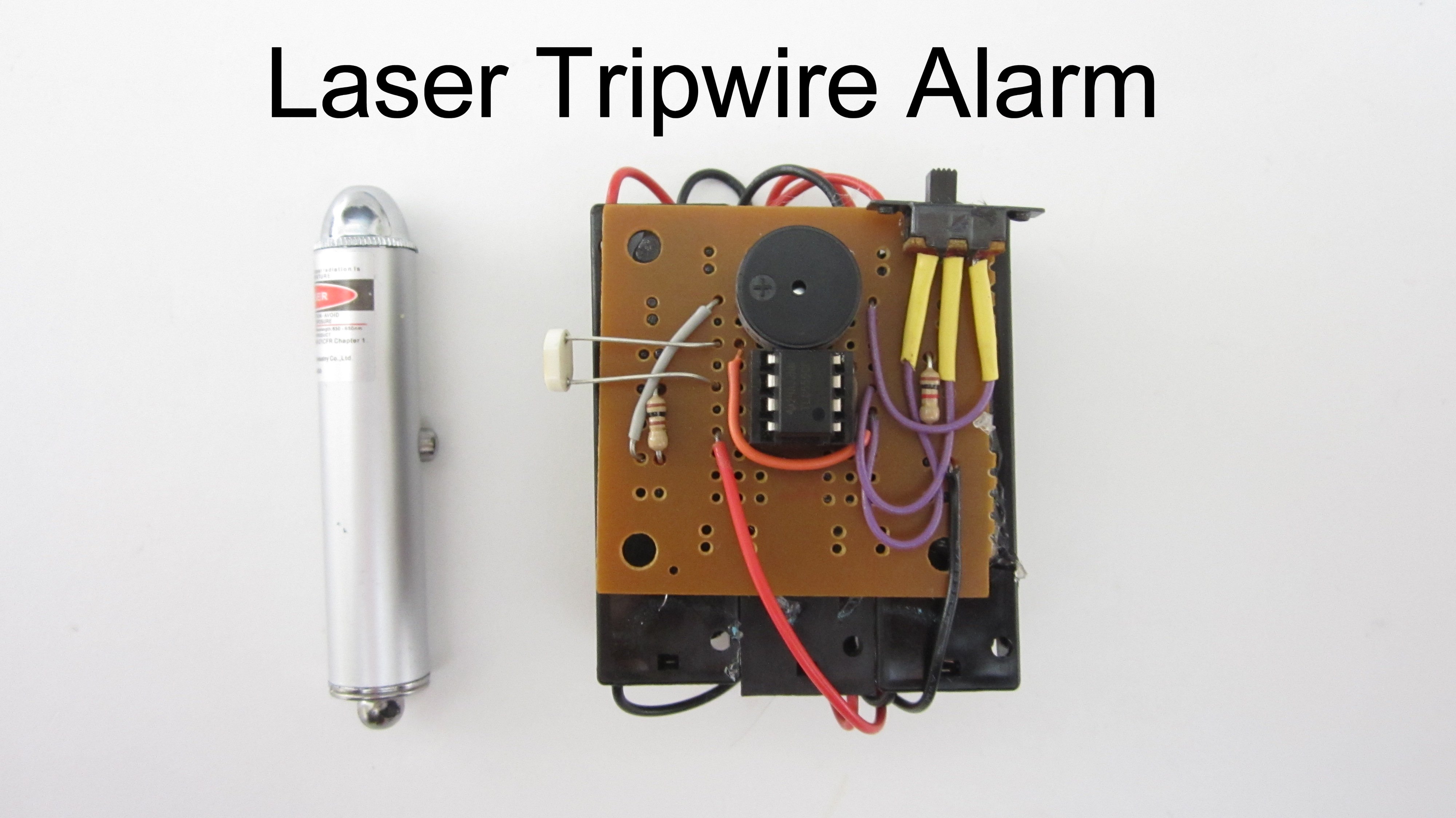
Assemble the Circuit

First assemble the circuit on a breadboard to test it. Set the switch to connect the buzzer. Without the laser shining on the photoresistor, the alarm should sound. Flipping the switch the other way should turn off the alarm. Now shine the laser pointer on the photoresistor and flip the switch one more time to reactivate it. As long as the laser is centered on the photoresistor, the alarm shouldn’t sound. But when you move the laser away, the alarm should go off again.

If everything is working properly, solder it all together on a printed circuit board. The board that I used is a general purpose IC board. These are really convenient for circuits that are built around small ICs like the 555 timer. I also used an IC socket to attach the IC. This makes it easy to change out the IC but it is not necessary.

The batteries are mounted in individual AA battery holders. The three battery holders are soldered together in series and the end leads are soldered to the circuit board.

When attaching the photoresistor, I mounted it with the leads sticking out about one inch from the board. This makes it easy to make small adjustments to the position of the photoresistor after it has been mounted in place.

Once the whole circuit is soldered to the board, test it again to make sure that everything is working properly.

Secure the Loose Parts to the Board with Hot Glue

The switch and the batteries are connected to the board with wires. I used hot glue to secure them to the circuit board. This helps to keep the whole circuit neatly together. If the wires from the battery holders are too long, you can tie them down with either tape or a rubber band.

Mount the Laser Pointer and the Alarm Circuit to Form a Single Beam Tripwire

The simplest way to set up your alarm is as a single beam tripwire. In this configuration the laser pointer is mounted to one side of the walk way and the alarm circuit is mounted to the other. For the tripwire to work, the laser pointer needs to be constantly on. The easiest way to accomplish this is by tightly wrapping a piece of tape around the button.

To secure the two pieces in place, you can use tape or a temporary adhesive putty such as Sticky Tack. First mount the alarm circuit in place. Then mount the laser pointer to the opposite side. Carefully adjust the position of the laser pointer so that it is pointed directly at the photoresistor.

Once you have the light from the laser pointer centered on the photoresistor, you are ready to arm the alarm. Flip the switch to connect the buzzer and activate the alarm. Whenever someone walks through the beam, the alarm will go off.

Use Mirrors to Make a Multibeam Tripwire

A single tripwire beam works but with the addition of a few mirrors, you can have the laser crisscrossing all over the room making it impossible for someone to avoid detection.

To accomplish this, you will need a lot of mirrors. There are a number of places where you can get small cheap mirrors. One place is the auto section of your favorite big box store. They often sell plastic sheet mirrors that are designed to replace car mirrors. The major advantage of these is that you can easily cut them to any size and shape that you want. Another good source for mirrors is a craft store. Many craft supplies have a mirror finish. However, the surface is not perfectly uniform. So you won’t be able to get as many reflections before the beam starts to disperse.

To set up a multibeam tripwire, start by mounting the laser pointer. Then at the point where the beam hits the opposite wall, mount a mirror. You can use tape or a self adhesive putty. Position the mirror at a slight angle so that it reflects the beam in a different direction. Continue this process adding more mirrors until you are satisfied with the number of beams or the light beam is starting to disperse too much. The last mirror should direct the light to the alarm circuit.

Because this system is using one continuous laser, if any of the beams are interrupted, it will cause the alarm to go off.

Optional: Power the Laser Pointer with the Alarm Circuit's Battery Pack

Most laser pointers also run on 4.5V (three button cell batteries). If your alarm circuit is powered by 4.5 volts (three AA batteries), then it is possible to power the laser pointer from this battery pack as well. All you have to do is connect the terminals of the laser pointer to the batteries of the alarm circuit.

One terminal of the laser pointer is a spring that sticks out of the internal circuit board. The other terminal of the laser pointer is connected to the inside of the metal barrel. You can easily connect to both of these with a pair of alligator clips. The alligator clips can be connected to the positive and negative lines on the circuit board, or you can connect them directly to the terminals of the battery pack.

By connecting the laser pointer to the larger battery pack you can extend the battery life and you only need to worry about changing one set of batteries.

Optional: Connect Your Laser Tripwire to a Larger Security System

The buzzer on the alarm works to alert you if you are nearby. But you can also connect the tripwire to a larger security system. As part of a whole house security system, you have more options in how the system alerts you. If also lets you confirm the alert with other sensors.

To connect your laser tripwire to another circuit, connect the grounds of both circuits. Then connect the wire that was attached to the negative terminal of the buzzer to the signal input of the second circuit. Set your monitoring circuit to look for a LOW signal. For example, if you are using an Arduino, wire it to a digital input pin and use the digitalRead function monitor the wire. When it detects a LOW signal have it activate the alarms.

There are a lot of systems that you can connect to. One example is the Cellular Sensor Sentinel. You can find the details of this weekend project at the Make Project page. https://makezine.com/projects/cellular-sensor-sentinel/