I have always hated mowing the lawn. I was the guy who only mowed when the grass got to be 6″ taller than the neighbors’ lawns — not because I don’t like my neighbors, but because mowing was such a pain. After being hit by one too many rocks, I decided I no longer wanted to stand behind a mower while cutting the grass. I also realized that if I got a riding mower, I’d still be right in the middle of all that dust and pollen.
I started thinking, what if I could mow the grass from the back deck, or even the computer? To handle my 1-acre backyard’s hills, dips, and rocks, an R/C lawn mower would have to be very sturdy, be controllable from a good distance, and have enough battery power to last several hours. I built the Lawnbot400 to meet these criteria.
Resources
Functional Overview
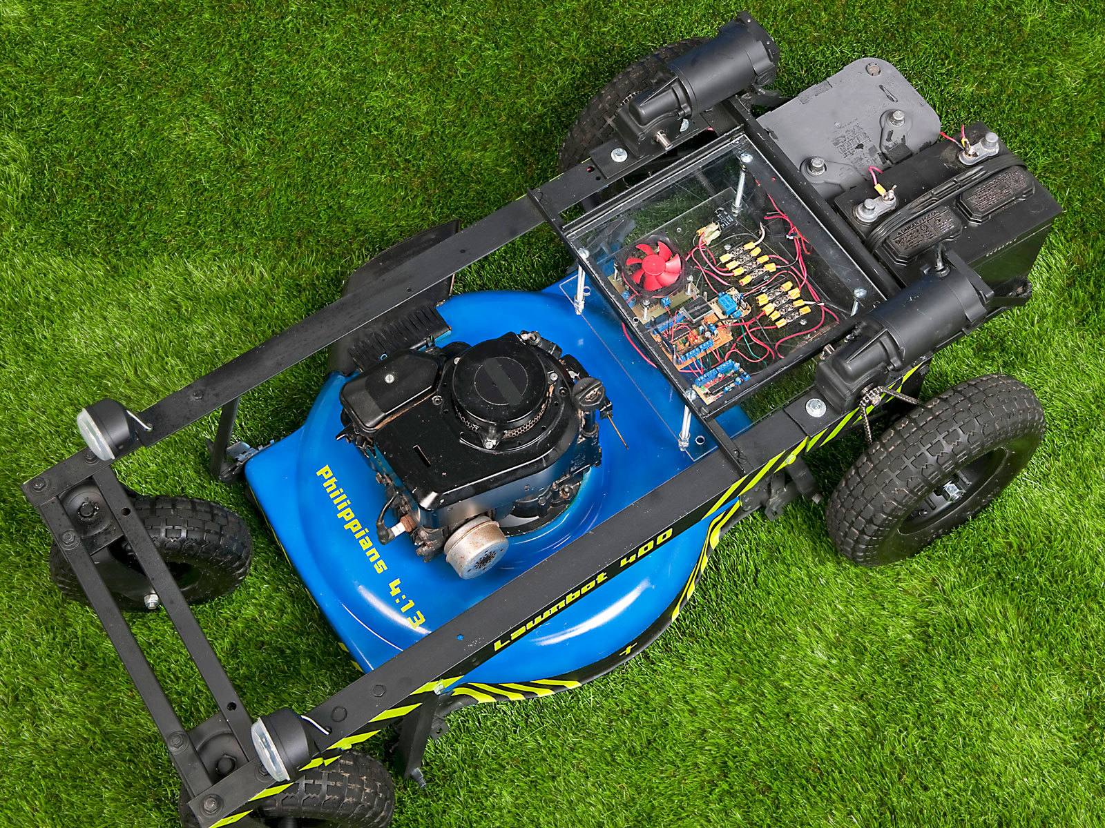
Basically, if you took the wheels and handlebar off any old gas-powered push mower, bolted it into a sturdy metal frame with 2 electric wheelchair motors, and added the electronics needed to make it move, you’d have the Lawnbot400. I control mine with a standard hobby R/C transmitter and receiver, but with just a few modifications it could be made autonomous.
Steering the Lawnbot is simple. Move the left control stick up, and the left wheel moves forward. Move the right control stick back, and the right wheel moves backward. Both sticks forward and you go straight ahead. This is called “tank steering,” and it gives the Lawnbot400 a zero turn radius.
The pieces that enable this control are a bit more complex. The hobby R/C transmitter encodes the control sticks’ positions and sends them to the receiver using pulse-position modulation (PPM), which encodes a value, such as the desired position of a servo, as the ratio of ON time to OFF time in a fixed-duration series of repeated pulses. But the H-bridge motor controller that supplies variable voltage to the wheelchair motors needs a simpler pulse-width modulation (PWM) signal, in which the pulses don’t repeat within a fixed time frame. So I used an Arduino-based microcontroller to translate the PPM R/C signal into PWM for the H-bridge.
The H-bridge uses transistors to convert the 0V–5V PWM values into straight 0V–24V DC voltages running from the batteries to the motors in both directions. The wheelchair motors are electric, so the bot will drive even if the gas-powered mower isn’t running. Instead of buying an H-bridge, I chose to build my own. (It should be noted that I didn’t plan to take the easiest route in this project. Instead, I wanted to learn how each electronic part worked, so I’d know how to fix it if it broke.)
I didn’t want to donate my Arduino to the project, so I made my own controller with screw terminals on each pin for secure connections during bumpy rides. Like an off-the-shelf Arduino, this board serves as a breakout board for the ATmega168 microcontroller chip, and it has its own 5V regulator (LM7805), 16MHz crystal, power LED, and reset button. I also added a header to the board for my R/C receiver to plug directly into. My board lacks the standard Arduino programming port and FTDI USB chip, so to use it, I simply program an ATmega chip in my Arduino, then swap it over.
With all of the above, I got the Lawnbot400 running successfully, and in the next version, I added a fail-safe to keep the bot from running away if it loses its signal. The fail-safe uses a second (even simpler) Arduino-compatible breakout board to read a third R/C channel, controlled by a toggle switch on the transmitter. The code reads this channel using the PulseIn method and sets a digital output pin accordingly. If signal is present, the output pin stays on, which uses a 5V relay circuit to keep a 60-amp relay open, to let the main 24V battery power reach the motor controller. But if the bot gets out of range or the switch is turned off, the channel reads LOW and motor power shuts off until signal is restored.
Both the R/C and fail-safe control boards were simple to build and cost around $12 each. Later, I figured out how to add fail-safe handling into the main R/C code, so you could use just one microcontroller chip with all 3 channels, but this would sacrifice some safety. If the sole ATmega goes crazy and stops responding, you’re out of luck, whereas it’s highly unlikely that both chips will fail at the same time. So I still use the separate, dedicated fail-safe.
Here’s how I built my latest Lawnbot400; see the Substitutions box on the previous page for easier options that will have you mowing from your deck chair sooner.


