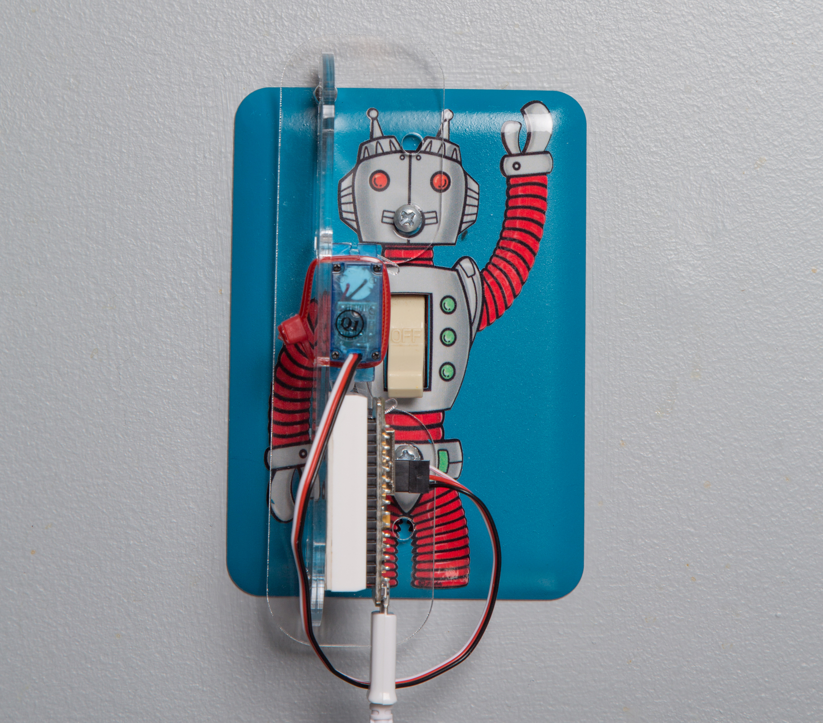
Photo by Hep Svadja
Photo by Hep Svadja
M52_Cover_LoRez
Read articles from the magazine right here on Make:. Don’t have a subscription yet? Get one today. On the cover: NASA’s JPL is using VR tech to create the next Mars rover. Illustration by Viktor Koen.

Here’s the problem: You have a light switch on your wall that you want to control over the internet. But you don’t want to mess with the house wiring — scary! — or damage the switch. What do you do?

Answer: Use a mechanical, motor-driven “finger” to flick the switch for you. As a bonus, you can still flip the switch normally, and can easily remove it when you’re done — essential if you rent your home. As with many engineering problems, it’s a tradeoff — you have an “internet thing” externally attached to your light switch. But if you don’t want to mess with house current or open up the light switch to conceal the apparatus, this is the way to go. It’s fun to have a tiny robot dedicated to flipping a switch whenever you say!

You control the Turner Onner over your smartphone or computer, using the provided code. And it’s self contained — it doesn’t use a base station, and you don’t need to sign up to any services (or hope that any third party remains in business) for your switch to continue working!

The Turner Onner simply publishes a web page to your local network. You flip the switch by accessing this web page and pushing On and Off buttons there. If you want to control it outside your local network (over the internet from anywhere) you need to set up port forwarding on your router. (For security reasons this may or may not be a good idea; we leave that to you.)

Here’s how to make it.

What will the next generation of Make: look like? We’re inviting you to shape the future by investing in Make:. By becoming an investor, you help decide what’s next. The future of Make: is in your hands. Learn More.

Project Steps

1. RIG THE PLEXIGLASS SLED FOR YOUR SWITCH

Figure A
Figure A. Click here to download as a PDF

You can buy our kit, or cut your own parts from 1/8″-thick acrylic; just download the templates (Figure A) by clicking here. There are 2 common types of light switch, the flat rocker and the vertical lever or toggle, and we provide templates for each type. The principle is the same in both cases (Figures B and C).

Figure B
Figure B. Step shots by Anthony Lam
Figure C
Figure C

Assemble either the rocker sled (Figure D) or the lever sled (Figure E), using the two M3 screws and captive nuts. For the lever sled, also check which pair of mounting holes is the correct distance apart for your switch plate; these come in a “home” size, where the holes are closer together, and a larger “office” spacing.

Figure D
Figure D
Figure E
Figure E

2. ADD A SERVO AND “FINGER”

For the flat rocker switch, the servomotor lies flat, parallel to the wall; mount it to the sled using the two M2 screws (Figures F and G). For the lever type, you’ll mount the servo vertically using 2 small cable ties (Figure H). This means the flat switch ends up looking nicer than the lever kind, but you probably can’t choose your switches.

Figure F
Figure F
Figure G
Figure G
Figure H
Figure H

Super-glue the acrylic servo “finger” to the servo horn (Figures I and J). Again, there are 2 different kinds of finger, depending on your switch.

Figure I
Figure I
Figure J
Figure J

3. INSERT MICROCONTROLLER

You could use a service that proxies to the internet for you, but we prefer using a super simple web server on your own local network. So we chose the ESP8266 NodeMCU, a nifty little $4 microcontroller with built-in Wi-Fi. Plug it into the mini breadboard, peel the adhesive, and stick the breadboard to the sled next to the servo.

Figure K
Figure K

The only thing you need to wire up is the servomotor. You can cut the end off the servo cable, split the wires apart, and just poke them into the breadboard. Or add a 3-pin male header to the connector (Figures G and K) — lucky for us, all 3 pins are next to each other. It’s really simple:

MCU Servo
Ground Ground
3v3 Power
D4 Signal

4. ADD ESP8266 SUPPORT TO YOUR ARDUINO IDE

The final step before testing is to add your network credentials to the code and upload it to the NodeMCU. That requires the Arduino development environment (make sure yours is up to date) with the ESP8266 board package.

To install the Arduino ESP8266 support files from GitHub, just open the Arduino IDE, go to File → Preferences and look for “Additional Boards Manager URLs.” Enter the URL http://arduino.esp8266.com/stable/package_esp8266com_index.json (Figure L) and then click OK.

Figure L
Figure L

Now go to Go to Tools → Board → Boards Manager. Scroll down to the ESP8266 listing, click anywhere in that block, and then click Install (Figure M). That takes a few minutes. When it’s done, click Close and restart the Arduino IDE so the settings can be refreshed.

Figure M
Figure M

5. PROGRAM THE MICROCONTROLLER

Download the Turner Onner project code from GitHub. It’s based on a simple ESP8266 Web Server program. To modify the sketch to add your own Wi-Fi network, just open it in the Arduino IDE and find these 2 lines:
const char *ssid = “”;
const char *password = “”;

and add your network name (SSID) and password inside the quotation marks.

Change the board type to NodeMCU 1.0 wth Tools → Board → Node MCU 1.0 (ESP 12E Module). Hit the Verify button and it should compile with no problems. Be aware that doing this erases the NodeMCU, and if you want to use Lua to program this board, you’ll need to reflash it. The board is now Arduino-ized (cue maniacal laughter!).

Finally, connect your board to your computer using the Micro-USB connector. If you have a Mac or Windows 10, it should register within a few seconds. (Windows 7 can take several minutes.) Eventually you’ll see the relevant port under Tools → Port. Select it.

Hit the Upload button and wait for it to say “Upload complete.”

6. CONNECT TO THE INTERNET

You’re all set. The only problem left is finding out the IP address that your router has given to your tiny new web server. In the Arduino IDE, click the Serial Monitor button at top right, and make sure the speed is 115200, or you’ll just get garbage. Connecting the serial port automatically resets the NodeMCU.

Stuff will be printed to the serial port, including the IP address (Figure N) — probably something like 192.168.1.3 (the last two digits are probably different).

Figure N
Figure N

Point your web browser to that IP address by cutting and pasting it into the address bar just like a normal URL. Voilà — the Turner Onner web page (Figure O)! You should be all set. Go ahead and try out your new On and Off buttons.

Figure O
Figure O

7. ADD POWER AND START FLIPPING

We have to get power from somewhere. Since we don’t want to get it from the 110V supply, there are two choices: battery or a wall-wart power adapter. The wall-wart is a little unsightly, but it will operate indefinitely. Plug it into the NodeMCU (Figures P and Q). Whoo! You’re off to the races.

KID FRIENDLY

Because the Turner Onner draws only minimal power from USB, it’s safe for kids’ rooms. Try decorating the servo finger with a robot hand, dragon claw, superhero, or other favorite character that will move when the Turner Onner flips. Or just get a fun robot switch plate, like this one that we found at Maker Faire Bay Area, made by Natalie McKean.

Questions? Ask us at support@wickeddevice.com. And have a great time flipping your Turner Onner.