Wind chimes capture wind energy to move metal tubes that generate sound when they strike one another. They’re simple, timeless, and beautiful. You can never predict the composition the chimes will play after the next gust of wind, which is what makes these inventions so compelling. The elegant overlay they add to our experiences brings us closer to nature.

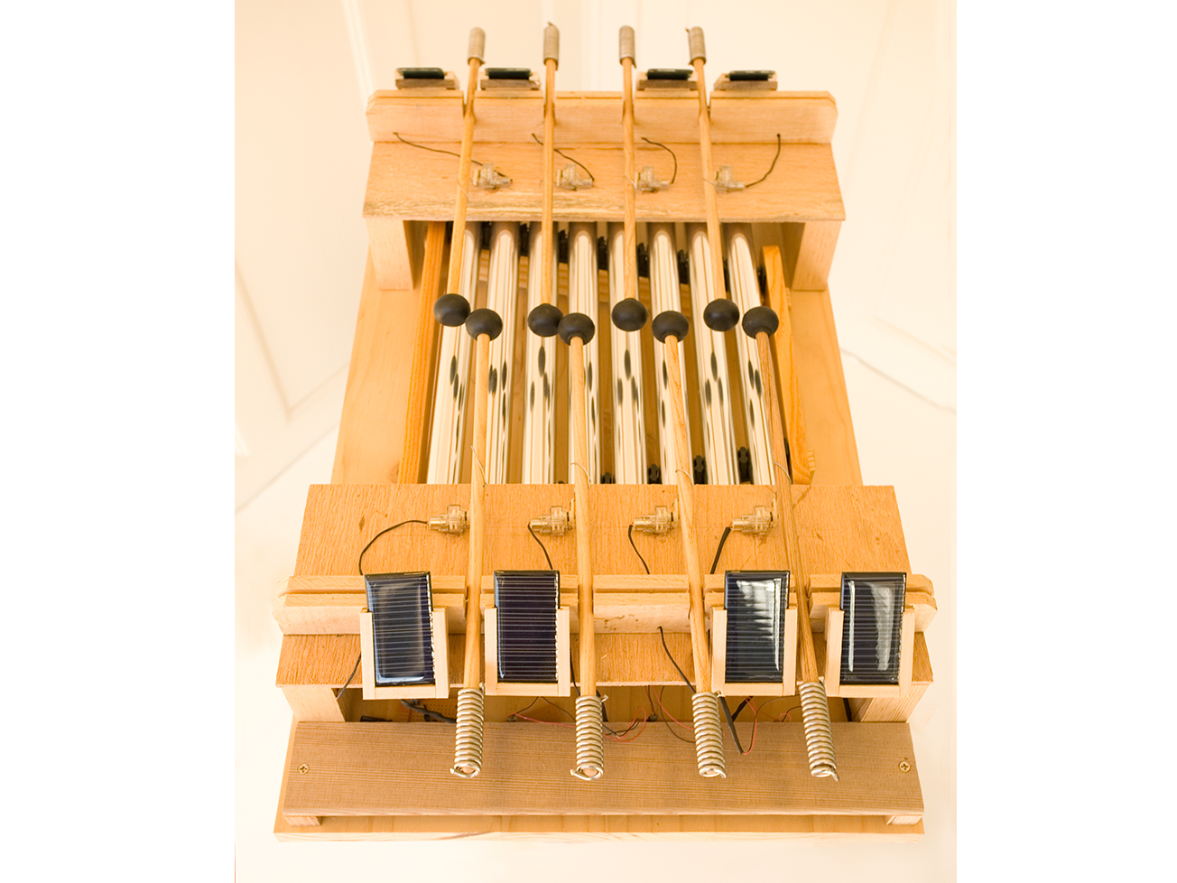
I wanted to create a different kind of autonomous musical instrument that would, like wind chimes, generate tones from a natural resource. So I made this solar xylophone, which gives voice to the silent sun and takes the project (and ourselves) outside, where we belong. It uses eight simple, independent systems to strike its eight chimes in parallel.

Notes-and-Circuit

Project Steps

Ready the perf board and parts.

Split your RadioShack perf board into single squares, or if you’re using your own perf board, cut it into 2″x2″ pieces.

Collect and separate the parts needed to make each circuit: voltage trigger, transistor, trimpot, diode, 4,700µF capacitor, 1.0µF capacitor, motor, solar cell, a bit of wire, 2 female connection headers (optional), and a piece of perf board.

Solder a circuit together.

Take one group of parts and solder a circuit together, following the Solarengine schematic above. This can be a bit tricky but it’s good practice if you want to get better at electronics. I put the electrolytic capacitor and the trimpot at opposite ends, and included 2 female headers for connecting to the solar cell and motor at the edges.

Solder the wire leads.

After you finish one of the circuit boards, solder wire leads onto the positive and negative terminals on the solar cell. If you’re using headers, solder male headers to the motor’s delicate leads (we don’t need these for the solar cell — the 22-gauge wire is thick enough).

Test the circuit.

Test your first completed circuit board by taking it outside or putting the cell under a high-wattage incandescent bulb. You should see the motor move within 10 seconds. A compact fluorescent bulb or heavy-duty flashlight will probably also work but will take longer, and you might begin to think something is wrong with your circuit.

Fixes

If it doesn’t work, adjust the trimpot using a screwdriver, by turning it all the way in one direction or the other. This controls the efficiency of the circuit, allowing more electricity to reach the capacitor, and thus, adjusting the timing of the motor. One side of the trimpot resists all the electricity while the other resists none.

The circuit works correctly if the motor periodically turns about 60° and then quickly resets itself. If it works, pat yourself on the back, call up your friends for help, and build 7 more just like it (or however many your project calls for). Otherwise, check your solder connections, review the circuit, and use a multimeter on the solar cell and 4,700µF capacitor to see if electricity is flowing. Lastly, ask a friend to review the circuit.

Cut the platform wood.

Cut 2 pieces of 1/8″ plywood to 5½”x15¼” each. These pieces will make the platforms that the mallet and motor mechanisms rest on.

Cut the platform legs.

Cut 4 pieces of the 1¼” wood to 3 1/16”x5½” . These will be the legs that support the mallet platforms above the xylophone.

Make wood cuts.

Cut 1 piece of 3/4″ wood to 16″x25 3/4″. This is the largest piece of wood and will support the entire structure.

Take the 1″x1 1/2″ wood plank and cut 2 pieces 15 1/4″ long each.

This is the tricky part. Now we’ll need to put a 1/2″-deep cut along the entire 1″ edge of each 1″x1 1/2″ piece. A table saw is perfect for this. Place each piece on the table with the narrow edge down, adjust the fence so that the blade is centered on the wood, and run it all the way through the piece. Repeat for the second piece.

Move the pieces back to the radial saw and cut four 5/16″ slits into each, 2 1/4″ apart, on the same side as the long groove. These will be the notches that hold the mallets. Start at one end of the piece and measure 3 3/16″ from the end. Mark off a section 5/16″ wide and 7/8″ deep. Measure 2 1/4″ from the marked section and repeat the marking 3 more times. Repeat this step for the second piece.

Glue the 2 plywood platforms on top of the 4 leg pieces to make 2 U-shaped raised platforms. Then glue the platform tops onto the large piece of 3/4″ wood, running parallel and centered 2 3/8″ from each end. Let the glue dry if needed.

Glue the 2 slotted strips on top of the platforms, running parallel and 1 1/4″ in from the outside edges. You should now have a nice wooden structure that will house the xylophone inside, below the platforms. Each slotted wooden strip will act as a balancing point for 4 mallets.

Install the mallets.

Use a 1/16″ drill bit to drill 2 holes into each mallet, one 5 1/8″ from the rubber ball end, and the other 4 1/8″ from the bare end. Slide a 10-penny nail into the hole closest to the bare end.

Cut and bend your paper clips into the zigzag shape shown here using wire cutters and needlenose pliers. These wires will run through the holes closest to the mallets’ striking ends and drive them from the motor.

Final Assembly

This part is particularly tricky. We need to figure out where the motors should be placed and how much counterweight (plumbing solder) to spool around the mallets’ ends.

Slide the xylophone in place under the platforms. Use your eyes to center it.

Place each mallet with its nail into its own groove on the balancing strips. The mallets should fall and rest on or near the center of each pipe. If not, adjust the placement of the xylophone underneath, or pull out and reverse the nail — the head can sometimes push a mallet off center. If that doesn’t work, check the alignment of the strips and the placement of the platforms. Handcrafting an instrument like this takes some tinkering.

Grab one of the mallets and wrap some plumbing solder around the wooden end. You want to wrap just enough to make the mallet balance nicely in the wooden groove and fall slowly down toward the xylophone, which requires trial and error.

Place a properly counterweighted mallet into the groove, and then bring the motor from one of your circuits close to the mallet head. Fit a bent paper clip into position, connecting the motor to the mallet, with the short end through the eyehole of the motor and the long end through the unused hole in the mallet. Curve the long end of the wire up and around the mallet.

Hold the motor slightly offset from the mallet, and make sure the motor is oriented so that it will pull down on the mallet.

Test the circuit while holding the motor in place. This will give you an idea if you’ve found the right spot. If so, mark its position on the platform with a pencil. Grab your Dremel tool, attach a round wooden shaving tip, and grind out the line you marked so that the plastic tab on the bottom of the motor will fit in it. The motor will then sit flush with the platform.

Repeat the installations and tests for all other mallet/motor/circuit combinations. After each motor placement mark has been ground out, do one last quick test and then hot-glue or epoxy the motor into place.

Finally, drill a hole in the balancing strips next to each motor and thread the motor lead wires through. Hot-glue or epoxy the solar cells so that they rest at a 45° angle with the top touching the strip above the hole and the bottom touching the platform edge. Connect your solar cells and motors back to the circuit. You’re done!

Conclusion

This project first appeared in MAKE Volume 12, page 98.

Related Posts on Make: Online:

Giant Xylophone Table

http://blog.makezine.com/archive/2009/12...

Solar Kit Gift Guide

http://blog.makezine.com/archive/2007/12...