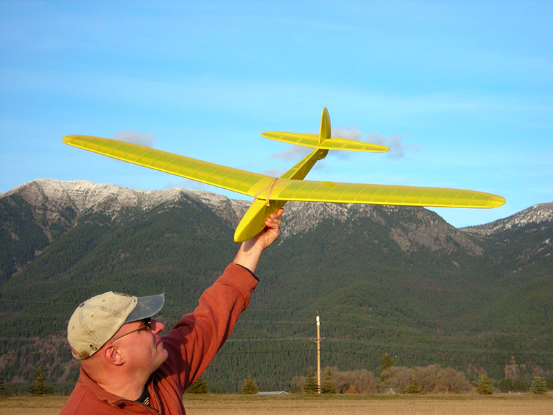
The summer before ninth grade, in 1985, I was stuck at home while my usual friends were away. I started talking with Eddie, the World War II vet who lived across the street, and during those 3 months he taught me the fundamentals of model airplane building. His lifelong hobby, which he had learned during the Great Depression, became my own, and it inspired my career as a flight instructor and developer of UAVs for the U.S. Air Force.

I designed the Medicine Man to reintroduce this largely lost art, drawing on my own experience and discussions with fellow modelers. I made it a glider because gliders are the purest form of flying machine, they’re cheaper to build, and they develop piloting skills without the distraction of engine management. It’s R/C compatible so you can fly it in city and suburban parks, or you can make a free-flight version for larger expanses. Its 5-foot wingspan makes it stable enough for beginners (larger planes are more stable), yet with the wings dismounted it will fit in a small car. I hope you enjoy it!

What will the next generation of Make: look like? We’re inviting you to shape the future by investing in Make:. By becoming an investor, you help decide what’s next. The future of Make: is in your hands. Learn More.

Project Steps

Trace the patterns

This is the tedious part. Do not attempt it while feeling impatient or agitated.

If you’re building from plain wood rather than the kit, download and print the plans from cdn.makezine.com/make/17/medicine-glider.zip. Trace the patterns onto the sheet using carbon paper, making sure the wood’s grain runs in the piece’s dominant direction. Mark some pieces multiple times, following the plan. I offer the kit http://www.realkits.com to save the builder money and because patterns can be frustrating to a beginning builder.

Cut the sheet parts

Cut out each piece using the knife. Cut them slightly oversize, particularly on mating portions, so you can sand them down to a firm fit later. Don’t cut through the piece all at once; allow several passes (2-3 per 1/16″ of thickness). Where parts are mirrored right and left, cut one and then flip it over to use as a pattern for the other. Old magazines are good for cutting on top of.

After cutting out each part, number it with a pen. Then trim the parts down and refine their shapes using sandpaper. Save leftover wood.

Build the tail

General building advice: Before touching knife to wood, study the plan and conduct an “imaginary build” of the model’s entire skeleton, visualizing each step. Taking the time to do this first will make the build much easier.

For each section of the plan, you’ll follow the same general procedure: pin the plan onto the building board under a sheet of waxed paper. Start with the tail, which is the simplest part.

Fit, glue, and pin down the pieces, starting with the perimeter pieces and then filling in, sanding as necessary for a precise fit. Glue pieces only after they’re snug; glue should work as a bonding agent, not as a filler. Wipe away excess glue with a scrap of balsa – this is easier than sanding it away later. Finally, spray down the assembly with warm water to relax tensions in the wood.

Let the tail assembly dry overnight and remove it from the plan.

Note: you can add 50% rubbing alcohol to the water to promote saturation and relax the wood even more.

Cut the tail’s curved tips and hinge slots for the rudder and elevator

To cut the tail’s curved tips, hold the plan up to a light and pin it aligned over the assembly. Lay them down, plan on top, and punch through the paper with a pen at about 1/8″ intervals, following the curve to make a dotted line. Remove the plan and make a connect-the-dots cut, following the line. Finish by holding the elevator piece (H-1) against the fin and blending their combined outline into a smooth curve.

Draw and cut hinge slots for the rudder and elevator, centered as shown on the plan. Use sandpaper to bevel the leading edges of the rudder and elevator along their hinge lines, so they’ll rotate freely.

Sand all surfaces to the rounded cross-section shown on the plan.

Build the fuselage sides

You’ll build the 2 mirror-image fuselage sides one at a time.

For the lower longerons (the horizontal structural members which run the length of the fuselage), soak 2 of the 3/16” square sticks in hot water for 10 minutes to make them more flexible.

Assemble a fuselage side on top of the plan, as you built the tail above. Place perimeter pieces first, then the risers, and finally the diagonals, working in from each end. This sequence gives glue joints a few minutes to set undisturbed.

Fit pieces F1, F2, and F3 into each side, spray down the assembly with warm water, and allow to dry overnight.

Remove the assembly from the plan and repeat these steps to build the second fuselage side.

Pin the 2 sides together and sand their perimeters down so they match.

Drill two 3/16″ holes in each fuselage side as shown on the plan for the wing mount pegs. You can twist the drill bit through the balsa with your fingers.

Separate the sides and sand the bevel shown in the fuselage top view into the tail. This makes the 2 sides handed, mirror-images rather than identical.

Cut and pin the cross-members

Following the fuselage top view, cut the cross-members for stations 1 through 7. Note that stations 3 and 5 use spruce, and at station 4 the top cross-member sits about 3/8” below the top in order to clear the wing. Pin the bottom cross-members in place on the fuselage top view.

Attach fuselage sides to cross-members

Glue the far fuselage side to the cross-members at stations 4 and 5. Pin it in place through the bottom longeron and make it exactly vertical using the T square.

Glue the other fuselage side vertical to cross-members 3 and 4. Add the top cross-members at stations 3 and 5 and re-true both sides, if needed, by adding or subtracting pins. Let dry 1 hour.

Spruce cross-members can be pinned into their end grain, and you can daub glue into hard-to-reach locations using a pointy scrap of balsa.

Glue the rear fuselage together in a similar manner, clamping or pinning the back (station 9).

Readjust

Readjust for trueness along both sides. Pinch, glue, and pin the cross-members at the front (station 1). Check that the nose is square, and if it isn’t, “persuade” it into position with a heavy, upright object such as a brick or a full bottle. Daub a second coat of glue onto these front cross-members (they’re under quite a bit of stress), and allow to dry 1 hour. Spray down the entire fuselage and let it dry overnight, to further safeguard against the dreaded “banana” fuselage.

The nose

Glue 3/16” sheeting above and below the nose. The top center piece will be the equipment bay hatch, so just tack-glue this section. Add top and bottom “slivers” between stations 8 and 9, as shown in the fuselage top view. Sand the front of station 1 flat, and glue on the nose block. Laminate and glue in the tow hook mounting block on the fuselage centerline aft of station 3. Let dry overnight.

Shape and sand

Shape and sand the completed fuselage. You can use the pen trick in Step 4 to shape the nose block. Lightly round the edges of the fuselage, except where the wing and tail will join.

Build the wings

You can build both wings at the same time if you have room on your building board. Be certain to build a right wing and a left wing, not two of the same!

Trailing edges

Pin the 1” x ¼” triangular trailing edge sections onto the plan, cutting and fitting the supporting pieces that curve forward at each end. Carefully mark and cut the 1/16” x 1/8” notches where wing ribs R3–R15 fit into the trailing edge. A knife or razor saw will work, but a loose hacksaw blade is better.

Re-pin the trailing edges to the plan in place. Fit, glue, and pin down the supports, W1 and W2, and the spruce spar, sanding to match the plan if necessary.

Bottom center sheet and wing ribs

Add (cut, fit, glue, and pin) the bottom center sheet piece that lies aft of the spar and spans ribs R1 and R2 underneath. Add wing ribs R2 through R15. Let the glue set for 30 minutes, then fit and glue the hard balsa  1/4” square leading edge into the ribs’ triangular front notches. Pin and let dry overnight.

The ribs’ notches may need some sanding, but never force them into place!

Cut the tips

Cut the wings’ curved tips using the Step 4 method, transferring the curve to the flat undersides. Sand the tips smooth and round.

Sand spanwise the leading edge to a uniform semicircular cross-section, as shown on the plan.

A lot of aerodynamic activity occurs at the wingtips, so pay attention and do clean work.

Sand

Using the sanding block, sand an approximately 3° bevel into the wing roots where they will mate. Be very hygienic with making clean joints here: the wing center section absorbs more flight stresses than any other part of the aircraft!

Join wings

Pin one wing back to the plan and join it to the other wing by gluing together the inside edges of the center sheet pieces. Use a hardcover book or something similar to prop the opposite wing tip 6″ above the building board.

Spread glue generously over one side of the dihedral brace and clamp it into place, binding the 2 spars together. Add the R1 ribs, ensuring they assume an angle symmetrically between the ribs on either side. Let dry overnight. I accidentally cut the inside ends of the leading edges too short, so I filled the gap in between with a bit of balsa.

Use 1/16″ balsa to sheet the topside of the wings’ center sections, then turn the wings over and add the bottom center sheet piece forward of the spar. Allow to dry.

Test assembly

Use a foam-block sander to gently remove burrs and hard edges on all external surfaces, except for the hard corners where the wings and tail will mate to the fuselage.

Cut two 2 1/4″-long pegs out of the spruce dowel and round the ends. Insert the pegs into their holes in the fuselage. Mount the wings to the fuselage with rubber bands, using the pegs as end posts. Check for straightness both from the top and (especially) from plumb center rear, sanding where the wings meet the fuselage if there’s a discrepancy.

Pin the tail components temporarily into place to again check the fit and alignment, making small adjustments where necessary. Again do so viewing the complete airframe from plumb center rear.

Step back and admire your work. Hey, I built that! Have a beer and just check it out. This is a moment to be savored; allow yourself to do so.

Equip it for R/C (Optional)

Drill holes in the fuselage rear for the 2 pushrods to exit.

Mount 2 servos approximately where shown on the plan, using 3/16” x 3/8” spruce to conjure up a support framework for your system. Mount the pushrods to run to the servo heads unobstructed.

Cover it

Follow the instructions that come with your covering material. A single 72″ roll will cover the entire model if you plan ahead. Here’s the usual procedure for iron-on plastic.

Cut out and lay a piece of covering over a section of the airframe. Smooth out the covering. Use a 350°F iron to first tack down the corners, then seal down the perimeter. Shrink and smooth the entire section by working the iron gently over the surface. Repeat for all model surfaces.

Cut a fringe into any curved edges to seal them down without wrinkles.

Final assembly – Horns and hinges

If you’re using R/C, mount the control horns and hinges on the rudder and elevator. Locate the hinge slots you cut in Step 4 and re-cut them through the covering. Wood glue won’t stick to plastic, so you need to remove the covering anywhere you’re bonding to. For a model this size, I cut the hinges in half lengthwise.

Final assembly – Pegs and elevator

Glue the wing-mount pegs in place in the fuselage. Attach the wings with rubber bands.

Glue the elevator to the tail fin, and glue this assembly in its mount between stations 8 and 9. Attach it to the fuselage with 1 pin centered in its leading edge. While the glue is still wet, center it so each tip measures the same distance to a common midpoint centered on top, and then pin down the trailing end.

Final assembly – Adjust and trim

With the glue still wet, adjust and pin the rear stabilizer so that it lines up symmetrically below the wings. Let it dry 1 hour. Glue and pin the vertical fin centered in place, and use a T square to ensure that it’s perfectly perpendicular. Let it dry 1 hour.

Trim some hinge material, then glue it to attach the rudder to the vertical fin. Glue the ventral fin to the fuselage and use more hinge material to connect it to the bottom of the rudder. Run a bead of glue around all fixed joints on the model. Check for square along all aspects, and let dry undisturbed overnight.

IMPORTANT! To adjust the wing “washout” for flight at low glider speeds, the trailing edges of the wing tips need to be twisted upward. Prop up the wing trailing edges with scraps of balsa, and then tape or clip small weights to the other 3 corners of each wing. Iron out the resulting wrinkles in the covering, and allow to cool to “lock” the new angle in place.

Final assembly – For R/C

For R/C, install the radio receiver and battery in the nose, following the instructions. For gliders, I skip the switch and plug the battery straight into the receiver before flying. I had to take my older receiver out of its case and wrap it in plastic to get it to fit, but a modern mini receiver should fit with no problem.

For R/C, connect pushrods to the servo arms, center the trim switches on the transmitter, and turn on the radio. The servos will come alive and center themselves. Install the included hardware to hold the pushrods, then follow them back to place and attach control horns to the elevator and rudder. Connect the rods to the horns. Move the radio’s stick to make sure nothing hits anything else.

Final assembly – Tow hook and landing skid

For the tow hook, drive a 1″ screw into fuselage, following the plan. For the landing skid, use 2 more screws to attach the brass strip under the fuselage, then sandwich rolls of masking tape above the middle to make the strip spring. Ensure that the radio is fully charged, and mount the wings to the fuselage. That’s it!

Download the plans for Medicine Man and read more about model aviation at makezine.com/17/model_airplane.

Build a high-start catapult to launch your glider hundreds of feet in the air: http://www.instructables.com/id/Greenest…

For a small glider like this, use about 3-5 pounds of pull for your first launches.

Conclusion

Related Make: Online posts:

Using Paper Airplanes to Learn About Flight:

http://blog.makezine.com/archive/2010/01...

$2000 Homemade Airplane:

http://blog.makezine.com/archive/2010/01...

Medicine Man Glider in MAKE, Volume 17:

https://makezine.com/17/

Make: Projects Roundup

http://blog.makezine.com/archive/2010/07...