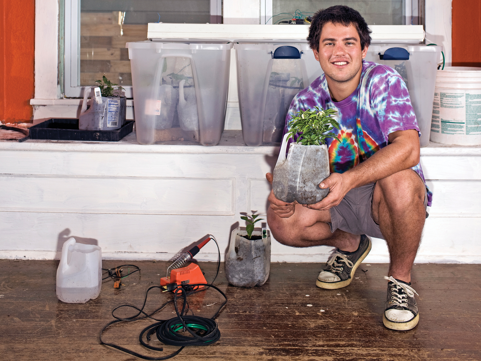
I wanted to start gardening, but I knew I wouldn’t keep up the regular schedule of watering the plants and making sure they got enough light. So I recruited a microprocessor and a suite of sensors to help with these tasks. An Arduino microcontroller runs my indoor garden, watering the plants only when they’re thirsty, turning on supplemental lights based on how much natural sunlight is received, and alerting me if the temperature drops below a plant-healthy level. For sensors, the Garduino uses an inexpensive photocell (light), thermistor (temperature), and a pair of galvanized nails (moisture).

Total cost, including the Arduino, was about $150.

All electronics can be purchased at the Maker Shed and Jameco, and everything else can be found at your local hardware store.

Project Steps

Microcontroller Overview

TIP: This project is ambitious for a first Arduino undertaking. I recommend completing at least the first few lessons of an Arduino tutorial before attempting this. There’s a great one at http://ladyada.net/learn/arduino.

WARNING: This project involves using electricity near water. We recommend connecting to a GFCI outlet.

Plant your garden.

Sprout your seeds before planting them, or buy started plants.

I planted a variety of vegetables in milk jugs with the tops cut off, with holes in the bottom to allow drainage, and a surrounding plastic storage container to catch water as it drained out.

Make moisture sensors.

Cut 2 pieces of wire, each 2’ long, and strip 1/2“ off the ends.

Wrap 1 end of each wire around the head of each nail.

Cover the wire-nail connection with a generous amount of solder.

Connect the moisture sensors to the Arduino.

You can tell when your soil needs water by measuring the resistance between the 2 nails stuck in the dirt. The more water in the soil, the more conductive it is.

Connect a wire between ground on your Arduino and the ground (–) column on your breadboard. You’ll use this column on the breadboard as ground for the rest of the circuit.

Connect a wire between +5V on your Arduino and the positive (+) column on your breadboard. You’ll use this column as the positive voltage connection for the rest of the circuit.

Connect one of the moisture sensors to +5V on the breadboard.

Connect the other moisture sensor to a new row on the breadboard.

Connect a 10kΩ resistor to the same row as the moisture sensor and also to a new row.

Connect a wire from analog input 0 on your Arduino to the same row as the resistor and moisture sensor.

Connect the other end of the resistor (in the new row) to ground.

Load the sensor test code.

Make sure that the moisture sensor works by connecting your Arduino to a computer and entering the sensor test code at https://makezine.com/18/garduino. When you touch the nails together, the moisture value should read ~985; when they’re not touching, the moisture value should be 0.

NOTE: If you haven’t used your Arduino before, you need to connect it via its USB cable to your computer, then launch the Arduino development application (free download at http://arduino.cc), enter the code, and then upload it to the board. Select the serial monitor to see the output.

Add the light sensor.

First, connect the photocell to 2 new rows on the breadboard.

Connect a wire between one row that the photocell touches and the positive column.

Connect a 10kΩ resistor to the other row that the photocell touches and to a new row.

Connect a wire between the photocell-resistor row and analog input 1 on your Arduino.

Connect the other end of the resistor to ground.

Test your light sensor by connecting your Arduino to your computer and monitoring the serial output. I measured the following values:

Indirect sun: 949

Ambient indoor light at night: 658

Ambient indoor light at night, with a hand casting shadow over the sensor: 343

Connect the temperature sensor.

Connect the thermistor to 2 new rows on the breadboard.

Connect a wire between one row that the thermistor touches and to the positive column.

Connect the last of the 10kΩ resistors to the other row the thermistor touches and to a new row.

Connect a wire between the thermistor-resistor row and analog input 2 on your Arduino.

Connect the other end of the resistor to ground.

Test your temperature sensor by connecting your Arduino to your computer and monitoring the serial output. I measured the following values:

61°F = 901

90°F = 949

51°F = 877

32°F = 796

Splice relays into the light/pump power cords.

Now we work with the heavy lifters: our relay setups. These will turn the lights and pumps on and off, in response to hours of sunlight received and soil moisture.

Cut four 10” lengths of 22-gauge wire and strip 1/2“ off each end.

Look at your extension cord’s plug: one prong is larger than the other. Split the 2 wires of the cord apart, then cut the wire that runs to the smaller prong, and strip 1” off each side.

TIP: The correct wire is the one without ridges running along its length. Don’t worry if you cut both wires; you can just splice the other wire back together.

Solder a 22-gauge wire to each side of the split cord wire.

Solder the 22-gauge wire that runs to the extension cord’s receptacle to the lower right lead of the relay (it should be labeled “4” on the bottom of the relay).

Solder the 22-gauge wire that runs to the extension cord’s plug to the middle left lead of the relay (labeled “1”).

Connect a 22-gauge wire to each of the 2 other leads on the left side of the relay (labeled “2” and “5”). Optionally, you can cover the relay’s bottom side with hot glue to strengthen all 4 connections.

Wrap both connections to the extension cord in electrical tape or heat-shrink tubing. Congratulations, you’ve completed your relay-cord setup.

Repeat the steps above with another relay and extension cord to create the second relay-cord setup.

Connect the relays and an LED to the Arduino.

Connect one of your diodes to 2 unused rows on the breadboard.

Connect the bottom left lead (pin 2) of your relay (looking at it from the top, with the leads down) to the positive lead of your diode — the end that does not have a band on it.

Connect the upper left lead (pin 5) of your relay to the negative lead of the diode — the end marked with a band.

Connect a wire between ground on your Arduino and the ground column on your breadboard (if you’re using the same breadboard for relays and sensors, just use the ground column you’ve already created).

Connect the row containing the negative lead of your diode (the end with the band) and the upper left lead of your relay to digital input/output 7 on your Arduino.

Connect the positive lead of the diode to your ground column. That’s it for connecting the first relay.

Now choose 2 new unused rows and repeat the steps above to connect the second diode and relay as you did the first, except this one goes to digital input/output 8 on your Arduino.

Connect the 220Ω resistor to 2 unused rows. Connect the LED’s long leg (+) to either end of the resistor, and its short leg (–) to ground. Connect the other end of the resistor to digital input/output 2 on your Arduino.

Set up the lighting system.

An easy step here: after checking that your light fixture is working, plug it into the relay cord that will control it.

I simply rested the fixture on top of the outer plastic bins, but feel free to get fancy.

Optimum distance from these fluorescents for the light intensity you want is just a few inches, so make sure you get them up close, personal, and adjustable as the plants grow.

Set up the watering system.

You’ve got a wide variety of options here. Here’s how mine works:

A small pump is submerged in a 5gal bucket water source.

A relay controlled by moisture sensors activates the pump to move water from the bucket to a milk-jug funnel.

Gravity moves water from the funnel down to the soaker hoses, which drip into the plants.

I used a mini soaker hose kit from Harbor Freight Tools to assemble rings that drip into all the plant containers. If you make a setup like this, be sure to elevate the bucket on a crate or something else; moving water inches instead of feet vertically will greatly reduce the strain on your pump.

I initially tried using just a sprinkler valve mounted to the bottom of a bucket, without the pump. But gravity provided only enough pressure for the slightest trickle. I thought about connecting the sprinkler valve right into my plumbing, but I worried that the chlorine content of water straight from the faucet would be bad for my plants (chlorine evaporates from water within something like 24 hours).

A better version of this would be to use 2 buckets, with water coming from a sprinkler valve connected to house plumbing going into one bucket, being held there 24-plus hours, and then moving into the second, plant-feeding bucket.

Program your Garduino.

Lastly, you need to program your Garduino to run the garden. Because temperature and soil moisture are dealt with as constants (i.e., always turn on the LED if temperature is below a certain value, always turn on the water if moisture is below a certain value) they’re simple to deal with.

Light is more complicated: you want to keep track of how much light your plants are getting, so that natural light plus supplemental light always equals optimum light time (in my case, I chose 14 hours daily). To do this, I used the DateTime Arduino library.

Switching to Gardening Computer

Reap Your Harvest

Check your seed packets (you saved them, right?) to see how many weeks until your plants should be ready for harvest. But don’t be surprised if they’re ready sooner than that! If they seem to be growing too slowly, check your watering and lighting routines.

Evaluate Your Data

As currently implemented, Garduino needs to be hooked up to a computer that’s monitoring serial output to obtain more meaningful data to share. With additional work, it’s possible to store data on a USB drive. But for now, monitor the serial output in the Arduino environment to evaluate your Garduino’s performance.

Improve Away!

I don’t expect this beta Garduino to get everyone gardening and save the world; that’s an exercise for readers to solve with their improvements. But here are some initial ideas:

Use pulsing red and blue LEDs for an ultra-efficient lighting system (see http://screwdecaf.cx/sept.html for Mikey Sklar’s version).

Figure out what times of night your utility charges lower rates for electricity, and turn the lights on during those times only.

Build a pH probe and fine-tune your soil acidity for different plants.

Add a relay-controlled heater to keep a greenhouse version above a minimum desired temperature.

Add a battery and solar panel to take the whole system off-grid.

Use an irrigation valve instead of a pump to water your larger, outdoor garden, and add some modified solar garden lights for additional lighting.

If many people start recording the efficiency and convenience of this automated approach to gardening, then maybe we can even grow more food of better quality with less energy. Happy Garduino-ing!

You can find the complete code at http://www.makezine.com/18/garduino. I’ll add links to better versions as readers create them.

Conclusion

This project first appeared in MAKE Volume 18, page 90.'''

Related Posts on Make: Online:

Android-Powered Garduino Remote Control

http://blog.makezine.com/archive/2010/03...

Original post: Gardening + Arduino = Garduino

http://blog.makezine.com/archive/2008/12...