M34_CoffeeBot_Groupshot

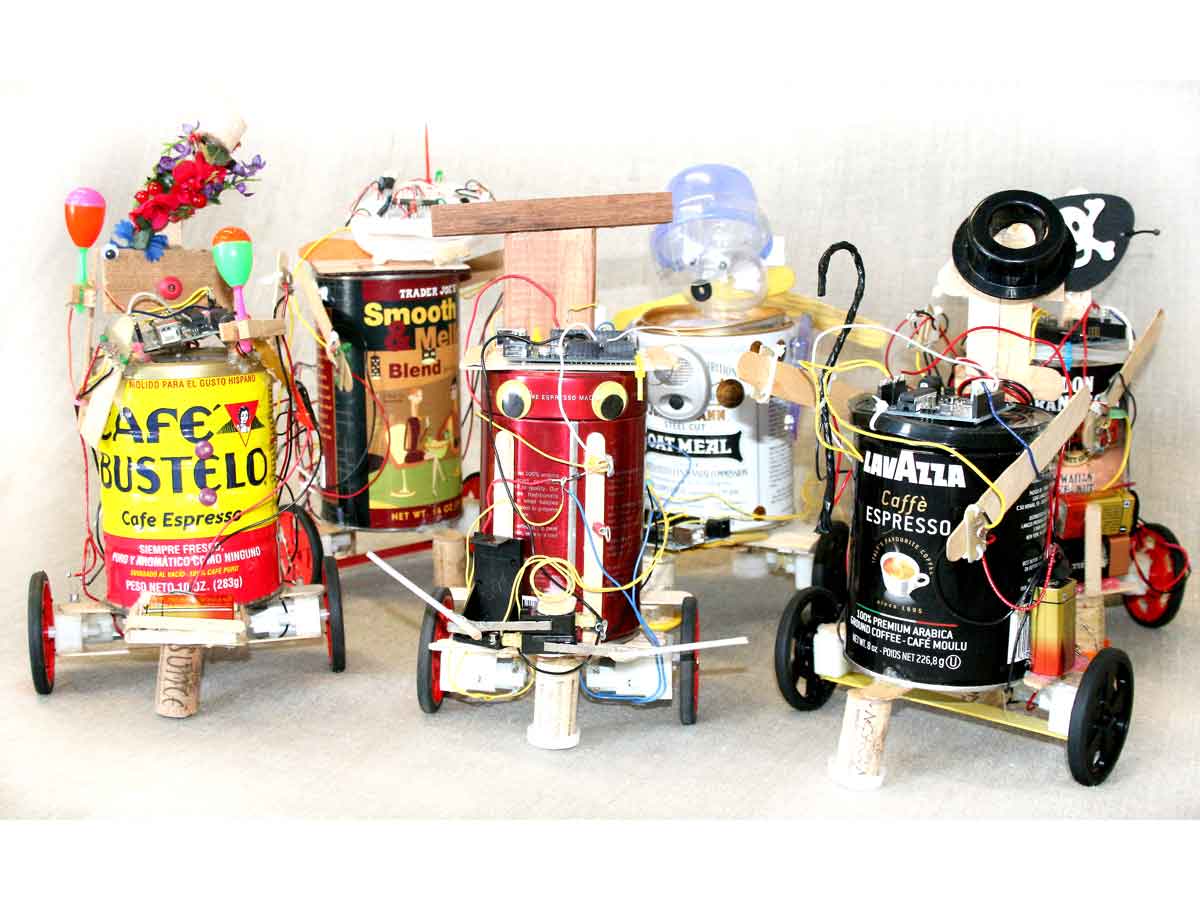
I created CoffeeBots to observe chaotic behavior, by programming a bunch of them with subtle differences and a few choices — for example, how to respond to light sensors — and then turning them loose. To distinguish one from another, I named them after celebrities or historical figures and gave them each their own personality and style. I discovered that their interactions can create patterns that resemble our own social behavior!

Each CoffeeBot is constructed from household materials that give it its own unique characteristics. Functionality comes from motors, sensors, wires, and an Arduino microcontroller for a brain. You can easily program your robot to detect light, to follow it or run away from it, to turn this way or that (by adjusting the timing of the motors), and to blink its LED light in whatever patterns you choose.

This robot was designed to get the most amount of robotic behavior for the least amount of coding, the least amount of money, and the fewest number of parts. And to be built by someone with the least amount of experience, in as little time as possible. You can definitely do this!

Project Steps

Wire the motors.

Attach a wheel to each motor shaft.

Position the motor heads facing each other. Strip the ends of 2 red and 2 blue wires, and hook these into the copper terminals: a blue wire to the bottom and a red wire to the top terminal of each motor. Solder all 4 connections. Hot-glue the wires to the motors for strain relief, as shown in the wiring diagram.

Caution: Take care not to rest the hot soldering iron on the plastic motor body, and not to overheat the copper terminals. Also, it’s wise to cover connections with electrical tape or heat-shrink tubing to avoid short circuits.

Build the chassis.

Hot-glue one 6″ solid craft stick across the top of both motors, and one across the bottom, for structural support.

For front-and-back stability, hot-glue a third craft stick perpendicular to the first 2. At each end, hotglue the wine corks and bottle caps as shown in the chassis diagram.

Note: Make the front cork slightly shorter than the rear cork, and allow the chassis to teeter. This ensures that the wheels will always be in contact with the ground.

Place your favorite coffee can on top of the chassis. Glue additional pieces of craft sticks as necessary to strengthen the connection between the chassis and the can.

Mount the terminal strip.

This is where multiple connections are made to the positive voltages (+9V and +5V) and to ground. Build the terminal post by gluing 2 small pieces of cork between a notched craft stick and a solid craft stick, then glue the solid stick to the back of the coffee can.

Label the notched stick for the 3 different terminal posts, from top to bottom: +9V, +5V, and Ground.

Make 2 light sensors.

Each sensor is made up of a photoresistor connected in series with a fixed resistor. Twist one leg of each component together, add a green wire, and solder the junction. The green wire will carry the signal from the light sensor.

Now solder the loose leg of the fixed resistor to a black wire, and the loose leg of the photoresistor to a yellow wire. Hot-glue each light sensor to a solid craft stick, then glue the stick to the can to make the robot’s arms.

Note: These resistors aren’t polarized, so their orientation doesn’t matter when you solder them together. But the assembled light sensor is polarized; you’ll connect it in the correct orientation in Steps 8 and 9.

Wire the transistors.

Look at the component with the tab up, the 3 legs down, and the part numbers facing you.

The left leg of the transistor is called the gate. Strip a white wire, twist the stripped end tightly around the gate leg, and solder.

The middle leg is the drain. Strip, twist, and solder the blue wire coming from one of the motors.

The right leg is the source. Solder it to a black wire.

Note: Make sure the wires don’t touch; you can bend the legs slightly to separate them. Wire the second transistor and motor the same way.

Mount the battery pack.

Depending on where you choose to mount the battery pack, you may need to extend its 2 wires to reach the terminal strip; they’re typically not very long. Hot-glue the battery pack in

place.

Wrap the black wire a few times around the Ground terminal location you marked, then strip its end to create your Ground terminal post.

Repeat with the red wire to create your 9V terminal post.

Important: Don’t put the battery in until you’re done wiring the robot and programming the Arduino.

Solder the power plug.

Unscrew the DC power plug’s cover and expose the 2 terminals. Solder a red wire to the inner terminal (+), and connect the other end to the +9V terminal post. Solder a black wire to the outer terminal (–) and connect it to the Ground terminal post.

Caution: Put electrical tape between the 2 terminals to avoid having them touch and short circuit.

Important: Thread the wires through the plug’s cover before soldering them to the robot’s terminal strip, so that you can screw it back on.

Connect the terminal posts.

Wire the remaining terminal strip connections, following the wiring diagram in Step 1. At your 9V terminal post, solder together the red wire from the battery pack, the 2 red wires from the top of the motors, and the red wire from the Arduino’s power plug.

For your 5V terminal, solder the 2 yellow wires from the light sensors, as well as a new yellow wire (which you’ll connect to the Arduino’s 5V pin in just a minute). You can wrap this new wire around the terminal strip to make it stay put.

And at the Ground terminal post, connect the black wire from the battery pack to the 2 black wires from the right legs of the transistors, the 2 black wires from the light sensors, and the black wire from the Arduino’s power plug.

Note: To avoid short circuits from exposed bare wires, only strip as much wire as is necessary to connect to your terminals.

Now you can tidy up your wires using the zip ties, and glue the transistors to the wooden arms if you wish.

Solder the headers for the Arduino.

Break off 3 strips of male header pins to fit the Arduino board’s female headers for Power (6 pins), Analog In (6 pins), and Digital I/O pins 0–7 (8 pins). These male headers have one row of short pins, to which you’ll solder your wires, and one row of longer pins, which you’ll plug into the Arduino.

In the Power block, solder the free wire from the robot’s +5V terminal post to your 5V header pin.

In the Digital block, solder the white wires from the 2 transistor gates to your Digital 3 and 5 header pins.

In the Analog block, solder the green signal wires from the 2 light sensors to your Analog 0 and 2 header pins.

The schematic diagram shows how these connections work (for one side only).

Tips: Solder the wires to the headers before you plug the headers into the Arduino. To avoid short circuits, make sure the wires don’t touch adjacent pins; I have intentionally avoided using adjacent pins to give you more room to work.

It isn’t necessary to twist the wires around the pins; it’s best to strip only 1/8″, apply solder separately to the wire and the pin, and finally, touch the wire to the pin and remelt the solder to form a good connection.

Add an LED (Optional).

Solder a black wire to the negative leg of the LED, typically indicated by a shorter leg and/

or a flat spot on the LED’s plastic dome.

Solder one end of a 220Ω resistor to the positive leg of the LED. Solder a purple wire to the loose end of the 220Ω resistor, forming a series circuit.

Solder the other end of the wire to a male header pin in the Arduino’s Digital block. You might wish to make an additional male header for Digital pins 8–13, and use pin 9 for the LED.

Solder the black (–) wire to the robot’s Ground terminal post. Then glue the LED wherever you want it on the robot.

Program your Arduino and install the brain.

The Arduino microcontroller will process all the inputs and outputs and control your CoffeeBot. Download and install the Arduino environment on your computer, following the instructions at arduino.cc/en/Guide/HomePage.

Then download the CoffeeBot code from bit.ly/coffeebot, and upload the correct version (with our without an LED) to your board.

Use the coffee can’s plastic lid as a tray for the Arduino, securing it with zip ties.

If your lid is metal, then make a tray from craft sticks, plastic, or other nonconductive material to avoid short-circuiting the board.

Plug your male headers into the corresponding female headers on the Arduino. Now your CoffeeBot has a brain.

Give it a nutty flavor and use it!

Now’s the time to go nuts with hot glue and googly eyes, pirate flags, or whatever bits you’d like to add to make it unique and fun.

Put a battery in, plug the power plug into the Arduino, and switch on the battery pack.

The CoffeeBot Arduino program makes your robot either seek or avoid light, depending on how it’s wired up. Shine a flashlight, or hold your hand over a light sensor, to change the robot’s behavior.

If you added the optional LED, the program will make the robot’s LED light up whenever the sensors measure equal brightness.

Try out this simple code first, and then

start modifying it to give your robot the

personality you desire. Position the LED so that other CoffeeBots can perceive the light, and see if they’ll react to it according to their own programming!

I designed the CoffeeBot as a platform for experimentation by adding other sensors. Maybe you’d like to add bump sensors, or distance measuring sensors, or infrared LEDs and detectors.

With these additional sensors, and suitable programming, it would be possible for robots to identify other robots and to follow, lead, or communicate with them!