M36_Proj_LiteBriteLEDClock_Opener

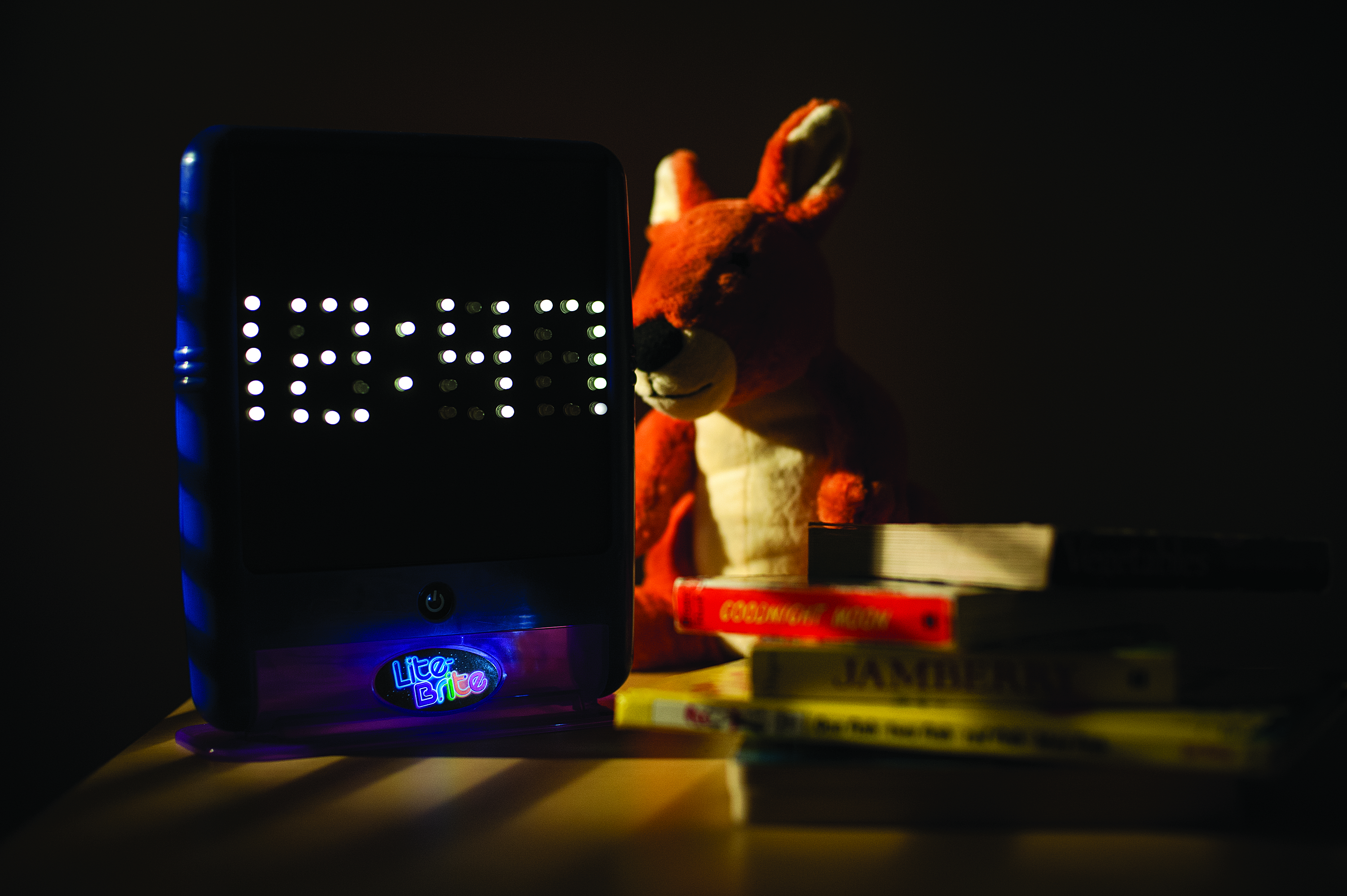
I just finished mentoring a high school student in the build of a 4×4×4 LED cube for his senior project. I was sitting at the desk, looking at a small pile of LEDs left over from the build, trying to think of something fun to do with them, when my three-year-old daughter walked in, sat down, and started playing with her Lite Brite. The pegs, I realized, looked just like LEDs, which was all the inspiration I needed. Let’s build a clock!

How Does It Work?

The challenge of this project is to discretely control 46 LEDs using a microcontroller that only has 20 I/O pins. The Lite Brite LED Clock utilizes common-cathode/common-anode multiplexing techniques and persistence of vision to lower the pin count demands on the microcontroller.

An array of 35 LEDs wired in common-cathode / common-anode configuration, as they would appear on a schematic diagram.
Schematic of 35 LEDs wired in common-cathode / common-anode array.

To light up a particular LED, set the row the LED is on to LOW and the column the LED is on to HIGH. The benefit to having LEDs arranged in a common-cathode/common-anode configuration is that we can use a relatively small number of microcontroller pins to discretely control each LED. The drawback to this arrangement is that we can only choose one LED to light at a time.

Persistence-of-vision based LED character display. With the limitations of human vision and the speed of the microcontroller, however, we can effectively light multiple LEDs simultaneously. To display the letter W, for example, we would light the first LED, turn it off, light the second LED, turn it off, and so forth until we have lit and unlit each LED in the W pattern. After the last LED is turned off, we start the process over again. The refresh rate is so fast that our eye sees all the LEDs as constantly on.

One effect of multiplexing LEDs this way is that they are dimmer than they would be if supplied with constant current. At first, I tried to supply the two dots of the colon with constant voltage since they would always need to be on anyway. The result: the colon was about ten times brighter than the numbers. The fix: assign the dots of the colon pins on the LED matrix, and turn them on/off at the same rate as the rest of the display.

What will the next generation of Make: look like? We’re inviting you to shape the future by investing in Make:. By becoming an investor, you help decide what’s next. The future of Make: is in your hands. Learn More.

Project Steps

Preparation and layout

If you haven’t already, take the two halves of your Lite Brite apart. Your Lite Brite may have an incandescent lamp holder or a bank of LEDs, depending on its model and date of manufacture. Remove the lamp, the lamp holder, and or any built-in LEDs and wiring from the back half of the Lite Brite so you’ll have plenty of room for new wiring and electronics.

If you don’t have any fresh sheets of black Lite Brite paper, cut a piece of black construction paper to fit now.

If you don’t have diffused LEDs, use sandpaper to buff the entire surface of each LED. The desired effect is for each LED to light itself up, rather than shining outward. Diffused LEDs also won’t make neighboring LEDs appear to be lit when they’re off like the clear ones will.

Use pegs to design the LED layout, then attach the black paper to the front of the Lite Brite and punch holes where the LED’s will go. Alternately, you can just poke the LED leads through the paper.

Solder the LEDs

NOTE: When building your LED matrix, insert the LED leads diagonally, as shown. This will make it easier to wire the rows and columns without crossing.

Install the top row of LEDs and solder the cathode (shorter lead) of each LED in the row together. Use a battery pack, resistor and alligator clips to test each LED before soldering to make sure the polarity is right and the LED is working properly. The cathode will be the lead that connects to the negative terminal of your battery.

Use pieces of hookup wire to connect cathodes that are too far apart to solder the leads together.

Repeat this process for each of the five rows of LED’s. Check your work by lighting each LED with your battery, resistor and alligator clips. This will help you to check the continuity of your solder joints and identify any shorts while they are still easy to find.

After you have all five rows of cathodes soldered together, solder the anodes in each column together. I stripped the insulation from a piece of hookup wire and looped it around each anode in the column. Squeeze the loop with your needle nose, then solder. Take care that your work is neat, and that your anode wires are not touching any of the cathodes. When you have finished all ten columns, test each LED again.

Connect hookup wire

Connect a length of hookup wire to each row of common cathodes and each column of common anodes. When you are done, you should have 15 hookup wires altogether.

Leave plenty of slack. The wires from the common cathodes are connecting directly to the Arduino. The wires from the common anodes are going to the perfboard first. You need to have an idea of where you are going to install the Arduino and perfboard in the case so you can leave the right amount of slack. Don’t forget you are also going to need enough slack to open and close the case.

Install the two LEDs for the colon. Solder the cathodes of these two LEDs together, and attach a length of hookup wire that connects them to GND. Solder one hookup wire to each of the anodes.

Add current-limiting resistors

We will be using a piece of perfboard to mount current-limiting resistors for the LEDs.

One side of the perfboard has the hookup wires coming in from the 12 common anode hookup wires; the other side has the hookup wires going to the Arduino. Everything is soldered together on the pads on the backside of the perfboard.

Connect the Arduino

Connect the 12 hookup wires from the perfboard to the Arduino. Connect the first column of anodes to Digital Pin 0 on the Arduino, the second to Pin 1, and so on for the columns up to Digital Pin 9. Connect the colon anodes to Digital Pins 10 and 11. From bottom to top, connect the rows of common cathodes to pins A0-A4.

NOTE: A0-A4 are often referred to as “Analog In,” but they are actually Analog or Digital I/O pins.

Close the case

Secure the perfboard and Arduino to the inside of the case with Velcro. Route a USB cable into the Lite Brite case through the light bulb access or battery cover on the back. The USB cable will provide power and allow you to set the clock, as well as upload the code to the clock.

Close the case, taking care not to pull out any wires from the Arduino. Depending on your Lite Brite model and where you put your Arduino, you may have to do a bit of hacking on the case interior to remove plastic walls or bosses.

Upload the code

Download the code from the MAKE Github repository and upload the test sketch to your Arduino board. If successful, you should see the clock count from 0-9 on all digits, allowing you to test each LED on your clock for proper operation.

Before you upload the code, you will need to set the time. In the “setup” portion of the code, the first line will read something like “setTime(9,27,0,27,7,2012);” where the numbers indicate hours, minutes, seconds, date, month, and year.

Set the correct time in the code and click the upload button .

NOTE: Keep in mind that the clock will revert to the time set in the code any time the Arduino is reset.

Conclusion

We only used 17 of the 20 I/O pins available on the Arduino Uno. This leaves 3 more pins to play with, perhaps by adding a button or two to set the clock or cause the date to be displayed. The code is already written to track the date, so instead of a button the display might be set to occasionally "flip" back and forth between the date and the time. You could also add an alarm function, maybe using a piezo speaker for a buzzer.

If you needed more pins, you could redesign the layout of the LED wiring to make a 7×7 matrix instead of the current configuration. This would make programming and wiring more complex, but the clock would only use 14 pins instead of 17.