


Sometimes there’s a tool you want to buy, but you can’t justify the cost. In that case, why not make it? For me, a plastic injection molding machine fell into that category — and it turns out they’re not hard to make.
I wanted to make solid plastic parts for some of my amateur science experiments. There are a number of ways to make things out of plastic, each with its advantages and disadvantages. Often just cutting raw material to the desired shape works best. Some plastics can be cast by pouring a liquid resin with hardener into a mold (see “DIY Rotocaster,” Make: Volume 41). Vacuum forming works well for making things out of thin sheets of plastic (see “Kitchen Floor Vacuum Former,” Make: Volume 11). I considered making a 3D printer, but for the few plastic parts I envisioned needing, it wasn’t worth the time and money.
Plastic injection molding has been around since thermoplastics were invented. It’s a great way to make many copies of a part quickly, and what I like best is that it’s easy to reuse old plastic objects to make new ones.
So I built an injection molder based on the plans in Vincent R. Gingery’s book Secrets of Building a Plastic Injection Molding Machine. David Gingery could be considered a forerunner of the Maker Movement — he and his son Vincent have written a whole series of books on building tools for the machine shop.
This project should cost between $100 and $200. It depends a lot on where the metal is purchased. I had a lot of the metal already, left over from other projects. Try to find a friendly local iron dealer, rather than getting the metal online or from a hardware store. They’ll often let you pick through their cut-off pile and sell it for almost scrap prices.
I wouldn’t recommend this project for someone who has no metalworking experience. I made full use of my machine shop: mill drill, lathe, stick welder, horizontal band saw, ½" reamer, and various taps. You can get by with a drill press and various hand tools. I welded most of the assembly together but the book calls for screws, except for one weld (which you could have someone else do if you don’t have a welder).
My Build

Being an engineer, I couldn’t resist making improvements. The plans call for a 1"×1½"×4" piece of cold rolled steel for the heater block (A), where the plastic is heated before being injected into the mold. I used a leftover piece of 1"×2" hot rolled steel instead. The wider block allowed me to add a second cartridge heater (B), so my machine warms up quicker and can get hotter.
The frame (C) in the Gingery design is mostly angle and flat iron held together with bolts and nuts, but two connections needed to be welded. So I decided to weld most of the frame and avoid drilling so many bolt holes.
The injection lever (D) pivots on a½”-diameter steel rod (E). I beefed this up by drilling larger holes in the frame and turning some steel bushings (F) on my lathe to support the rod. The bushings also keep the lever centered over the injection piston (G).
My favorite fastener for projects is Allen head cap screws so I used #10-24 cap screws instead of 1/4-20 bolts to mount the heater block and guide block to the frame. They’re at least as strong as ungraded 1/4-20 bolts and should conduct a little less heat from the heater block to the frame.
(One modification I tried didn’t work out so well. The heater block and guide block need to be spaced out from the frame a bit, to isolate the hot heater from the frame and put the parts into proper alignment with the piston. The plans call for washers, but I tried using some leftover fiber ceramic insulation sheet instead. It was too soft — it allowed the heater block and guide block to move out of alignment, preventing the piston from operating smoothly.)
Temperature Control Upgrade
The major deviation from the plans is the temperature control. In the original design, you have to watch a dial thermometer while fiddling with a bimetal thermostat. Going with something more modern is well worth the effort.
I used an inexpensive digital temperature controller (H) from Auber Instruments (auberins.com). These controllers use PID (proportional-integral-derivative) feedback control and can bring the temperature up to the exact setting quickly without any overshoot. I mounted mine in a separate enclosure and added a solid-state relay to handle the high-power heaters. A thermocouple sensor (I) comes with the controller; it screws into a tapped hole in the heater block near the nozzle (J). It is really nice to be able to set the desired temperature on the controller, turn on the heaters and watch the temperature rapidly climb to the setting.

Using the Injection Molder
Using the machine is easy. The book recommends making a test mold that will make two ½"-diameter pellets of plastic. These pellets are then used to feed the machine when making real parts.
To try it out I cut some ⅜"-wide strips of polyethylene from an old plastic tote lid, set the controller to 380°F and fed the plastic strips into the cylinder. After the cylinder is filled with sufficient molten plastic, the mold is placed under the nozzle and raised into place. (If the mold in put in place while the plastic is being loaded some of the plastic will dribble out of the nozzle and clog the sprue of the mold.)

Then pull the lever and inject! Here’s the pellet mold and some successfully injected pellets.


Some Tips
- Wear leather gloves when working with the machine. The heater block is quite hot and the mold warms up with use.
- It’s easy to apply too much pressure when injecting the plastic. Stop when you first feel additional resistance. If you apply too much pressure, plastic will squirt out of the mold and you’ll have a lot of “flash” on your part.
- I put a little oil on the piston where it goes through the guide block. Plastic can build up and make it sticky.
Making Molds
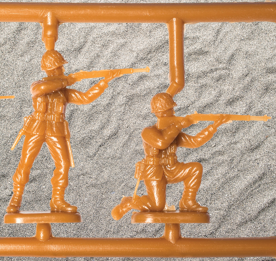
Now I’m making test-tube caps for my science experiments. I started out by drawing a sketch for the mold in my project notebook. The test tubes are 16mm in diameter so I started with that dimension and chose arbitrary dimensions for the height of the cap and thickness of the plastic. I added a lip to the cap to make it easier to pull off.
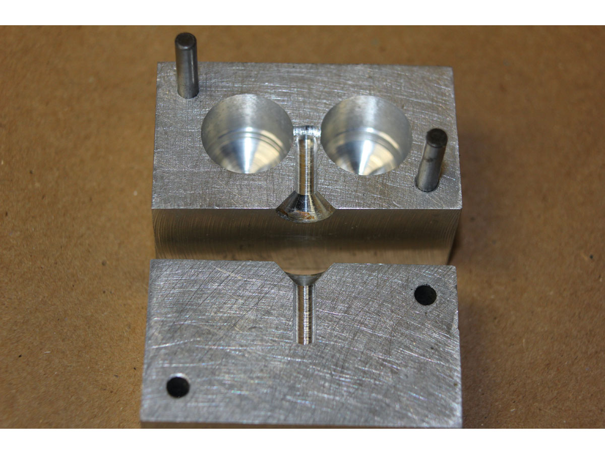
Once the sketch is made, I’m off to the machine shop to cut some metal. Two little blocks of 6061 aluminum make up the halves of the mold. First, two 0.124" holes are drilled through both blocks to hold guide pins that will ensure the mold halves are properly aligned. Two ⅛" guide pins are pressed into one half of the mold, and the other holes are reamed out just slightly to 0.126". Then the parts are machined on the lathe to form the cavity for the cap. Finally a sprue hole is drilled and countersunk.
I tried out the cap mold with some of the tote lid plastic I used for the test pellets. The caps turned out nice, but they were a bit stiff and difficult to put on. A more flexible plastic was needed. Then I made some caps with LDPE (low-density polyethylene) lids from oatmeal boxes. The caps made with the LDPE work just fine.


For now, I’m limited to simple molds I can make with a lathe or mill, but I’m adding CNC capability to my lathe, and thinking about a CNC router. That would open all sorts of possibilities.
Learn more: Secrets of Building a Plastic Injection Molding Machine by Vincent R. Gingery (David J. Gingery Publishing, 1997), ISBN 1-878087-19-3


