There’s something magical in the way that an inductive battery charger feeds current into a smartphone — or a car — without making an electrical connection.
How does it work? The answer is, the system takes advantage of a fundamental relationship between electricity and magnetism. You can see it for yourself with some simple hands-on experiments.
I’ll begin with that most humble device, the electromagnet, which merely consists of some wire coiled around a central rod called the armature. Figure A shows a 12VDC electromagnet available on eBay for under $6, capable of lifting about 5 lbs.
Figure A
A solenoid takes this concept a step further. It’s an electromagnet with a hollow armature and a separate plunger; which is pulled into the armature when you apply voltage. The plunger usually has a hole drilled at one end, for attachment to an external linkage — such as a lever or an arm. Figure B shows an example. You’ll need two solenoids to perform the induction experiment that I’m going to describe.
Figure B
To test it, insert the plunger halfway and apply a 9V battery. Clunk! The plunger is dragged all the way in.
Electromagnetism works because when DC current runs through a wire, it creates a magnetic field around the wire. This phenomenon was discovered accidentally in 1820 by Danish physicist Hans Christian Oersted, who noticed a compass needle moving when he applied power through a wire.
Figure C
If you bend the wire into a loop, the magnetic forces combine in one direction to form a flux, or magnetic flow, as in Figure C (where the flux is visualized in green). This is sometimes called “the right-hand rule,” because if you turn a corkscrew clockwise with your right hand, it moves downward into the cork. Likewise, if you apply current clockwise through a loop of wire, the magnetic flux pushes downward (assuming we imagine current flowing from positive to negative, and the flux running from north to south).
Now if you create multiple loops in the form of a spiral, you multiply the magnetic force. You can calculate it if you know the number of turns in the coil (N), the width of the coil (W), and the diameter of the coil (D). The approximate relationship is shown in Figure D.
Just as electricity can create magnetic flux, magnetic flux can create electricity. Almost all the power generation in the world relies on this relationship. Our civilization depends on magnetism.
You can use a neodymium magnet to demonstrate this right on your desktop. (These concepts will be familiar to you if you’ve read my book Make: Electronics, but in a moment, I’m going to take them further.) You need a cylindrical magnet measuring 1/2″ diameter and 1″ long, and a spool of magnet wire, which is thin copper wire with a very thin transparent coating.
The spool must have a hole in the middle, 5/8″ to 3/4″ diameter. Also, you must be able to access both ends of the wire. If your supplier hasn’t left the inner end poking out, you’ll have to rewind the whole thing.
Use very fine sandpaper to remove the insulation from each end. Be careful — the wire is fragile. Now solder some hookup wire of about 26 gauge to the ends of the magnet wire. The solder will only stick where you have successfully removed the insulation. See Figure E.
Figure E
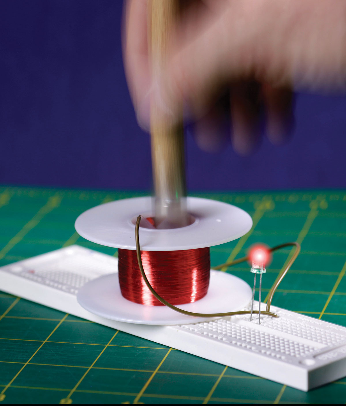
Strip the free ends of the hookup wire, apply a thin coating of solder, and you should be able to push them into holes in a breadboard. Place a low-voltage, low-current LED between them. Now power your LED by moving the magnet in and out of the spool rapidly, as shown in Figure F. This is easiest if you attach a wooden handle to the magnet. Use a 6″ length of 1/2″ dowel with a flat-headed screw inserted in one end. The magnet will cling to the screw.
Figure F
This teaches an important lesson. A constant magnetic flux doesn’t do the job. It has to fluctuate to induce pulses of current. In fact you are generating alternating current. Because the LED is a diode, it only responds to pulses in one direction. If you add another LED in parallel with the first but with opposite polarity, they will flash alternately.
To measure the voltage that you’re generating, set your meter to AC volts (not DC) and apply it across one of the LEDs.
You’ve seen that electricity can create magnetic force. You’ve seen that a fluctuating magnetic force can create electricity. So let’s cut out the middleman (the magnet) and put two coils face-to-face. Electricity running through one coil will create magnetism, and the magnetism will induce electricity in the other coil. They will have an inductive connection.
You can use your two solenoids to do this, although you’ll have to remove the metal cage enclosing each of them. I pried it off with a hammer and awl to reveal the coil inside, as shown in Figure G.
Figure G
To create a fluctuating magnetic field, the input power must fluctuate. A 555 timer (the old TTL version) can do this, powered with a 9V battery. A simple schematic is in Figure H. The trimmer potentiometer will vary the frequency between around 5KHz and 100KHz.
Figure H
Apply power to the timer, position the coils so that they kiss each other end-to-end, and check the voltage across the output coil. It will be only around 0.2VAC, because the two coils are not working efficiently. Try adjusting the timer frequency, and you’ll see some variation, but not enough to power an LED.
You need to channel the magnetic flux with armatures inside the coils. I found that inserting a 1.5″ x 1/4″ steel bolt in each coil would boost their performance, but not enough. What I needed was a pair of ferrite rods, although you have to get the right kind, because most of them are designed for radio frequencies. A ferrite rod is shown in Figure I, beside a bolt for comparison. Insert one rod in each coil and place the coils end to end, and you should see your LED light up. If it is very dim, rotate one of your coils 90 degrees relative to the other. Now you should get a bright output. Depending on your particular ferrite rods, some frequencies may work better than others.
Figure I
Through the magic of inductance, one coil really can power another. A picture of the breadboarded circuit is shown in Figure J.
How can you create the higher efficiency that you find in a real inductive charger? Increasing the frequency, increasing the voltage, using more turns in a coil, or using a larger coil diameter are some obvious options. You can also unwind the wires from the solenoids and wrap them directly around the ferrite cores. Or you can try to wind a pair of very wide, flat coils, which are the type used in charging equipment, and then “tune” the coils with capacitors and other components, although this is not trivial. Go to makezine.com/go/wireless-phone-charge/ for a tutorial that delves deeper into what’s involved.
PRECAUTIONS
Neodymium magnets are powerful. Keep them away from wristwatches, handheld devices, credit cards, computers, monitors, and — most of all — pacemakers.
By varying the number of turns in one coil relative to the other, you can change the output voltage. This is how a transformer works. But avoid generating a voltage much above 20VAC. High frequency alternating current can be dangerous. Think of it as the dark side of the electromotive force.
Our websites use cookies to improve your browsing experience. Some of these are essential for the basic functionalities of our websites. In addition, we use third-party cookies to help us analyze and understand usage. These will be stored in your browser only with your consent and you have the option to opt-out. Your choice here will be recorded for all Make.co Websites.
Allow Non-Necessary Cookies
Escape to an island of imagination + innovation as Maker Faire Bay Area returns for its 15th iteration!
Buy Tickets today! SAVE 15% and lock-in your preferred date(s).