IMG_6024

Microcontrollers such as Arduinos are a great way to control your custom electronics projects. But you always need some way to connect the external components to the microcontroller board. Jumper wires can work for this, but having too many loose wires running around is just asking for trouble. A good solution for this problem is to use some kind of a shield. This is a circuit board that uses a set of pins to connect directly to some (or all) of the pins on the microcontroller.

A shield is an easy way to connect all of your external components together. You can use shields to control motors, relays, LEDs, or anything else. You can even use proto shields to prototype your whole circuit directly on the board.

In this project, I’ll  show you how you can make your own custom shields for your microcontroller.

YouTube player

Project Steps

Select a set of header pins

All shields are going to use a set of header pins to connect to the microcontroller. The two most common types of header pins used on shields are male break away header pins and stacking header pins.

The stacking header pins are female header pins that have extra long pins. They are used on shields when you want to be able to stack other shields on top of them. They are also used when you want to be able to make temporary connections to the board with jumper wires. I purchased mine from Adafruit. They sell a set of stacking pins that match all the pins on a standard Arduino board.

Male break away pins are used on most other kinds of shields. They are small connectors that can easily solder directly to either the top or bottom side of the circuit board.

Select a circuit board

Most kinds of circuit boards will work for making a shield. The easiest kind of boards to use are double sided circuit boards. These have etching on both sides. This lets you make your connections on either side to suit whatever works best for your design. If you do not have access to double sided circuit boards, it is often possible to take two one sided circuit boards and mount them back to back. This will let you make connections on either side but it does take up a lot more space. I personally prefer to use plain perf boards because they let you make all the connections yourself.

How to make a proto shield

A proto shield is the most basic kind of shield. This is essentially just a plain circuit board with a set of attached header pins.

You just need to make one modification to the header pins before you can solder them to the circuit board. Most of the pin holes on the Arduino have the standard 0.1 inch spacing between each hole. However, this is not true of the spacing between pins 7 and 8. This spacing is slightly smaller. To compensate for this, you need to bend each of the pins slightly. By bending the pins you can make the tops match up with the standard 0.1 inch spacing on the perf board and the bottoms match up with the smaller spacing on the Arduino. For male header pins, you will want to bend the tops of each pin. For stacking header pins you will want to bend the bottoms of each pin. To ensure that everything lines up properly, I recommend inserting the pins into the Arduino before soldering.

Once your protoshield is finished, you can add parts and build any kind of circuit that you want.

How to make a relay shield

To create a basic relay shield, you start with the protoshield from the previous step. On to this, you will add the following parts:

  • 5V Relay
  • Diode
  • NPN Transistor
  • 1 kohm Resistor
  • 100 ohm Resistor
  • LED
  • Screw Terminal Connector
  • Jumper Wires

The relay coil is connected between the collector of the transistor and the 5V pin on the Arduino. The diode is connected in parallel with the relay coil with the cathode connected to 5V. An LED and resistor are also wired in parallel with the relay coil. This gives a visual indication of when the relay is activated. The emitter pin of the transistor is connected to the GND pin on the Arduino. The base pin of the transistor is connected to one of the digital pins through a 1 kohm resistor. Finally the switch terminals of the relay are connected to the screw terminals. This gives you an easy way to make temporary connections to the relay switch.

How to make a servo shield

To create a servo shield, again start with the basic proto shield. To turn the proto shield into a servo shield all you need to add are some header pin connectors, some jumper wires and a power connector.

To drive a servo motor, you need to connect the wires according to the following color code. The red wire is connected to the positive supply voltage. The black (or brown) wire is connected to ground. The third wire will be colored white, orange, yellow, blue, or black. This is the signal wire and is connected to one of the digital pins.

For low powered servos, you can power the motor directly from the Arduino. However, the Arduino can only output a maximum of 200 mA. So if you want to control multiple servo motors, or if your motor requires a lot of current, then you will need an external power source such as a battery pack. If your servo is rated to operate at 6 volts, then the easiest solution is a battery pack made from four AA batteries. The battery pack needs to be connected to the Vin pin and the GND pin on the Arduino. This will allow the battery pack to power the Arduino as well.

Now we need to add the header pins that will connect to the servo. I connected three sets of header pins to the circuit board just below the connectors for the digital pins. Take the top set of pins and use a bead of solder to connect these pins to the adjacent digital pin connectors. The next row of pins will correspond to either the positive wire or the ground wire on the servos. Use jumper wires to connect these pins to either the Vin pin or the GND pin (whichever is appropriate). Do the same for the third pin and connect it to either the Vin pin or the GND pin.

When you are working with multiple servos, you will want the positive servo wires to be connected together and you will want the ground wires to be connected together. You can do this by connecting the adjacent terminals with a bead of solder. If you find it too difficult to use the soldering iron between the header pins, you can push the end pins down. This will give you more room when soldering the center pins. You can then push the pin back up to the original height so that you can solder it in place.

You can now hook up your servo motors. Using this basic design, you can control up to 12 servo motors with a standard Arduino.

How to make a motor speed controller shield

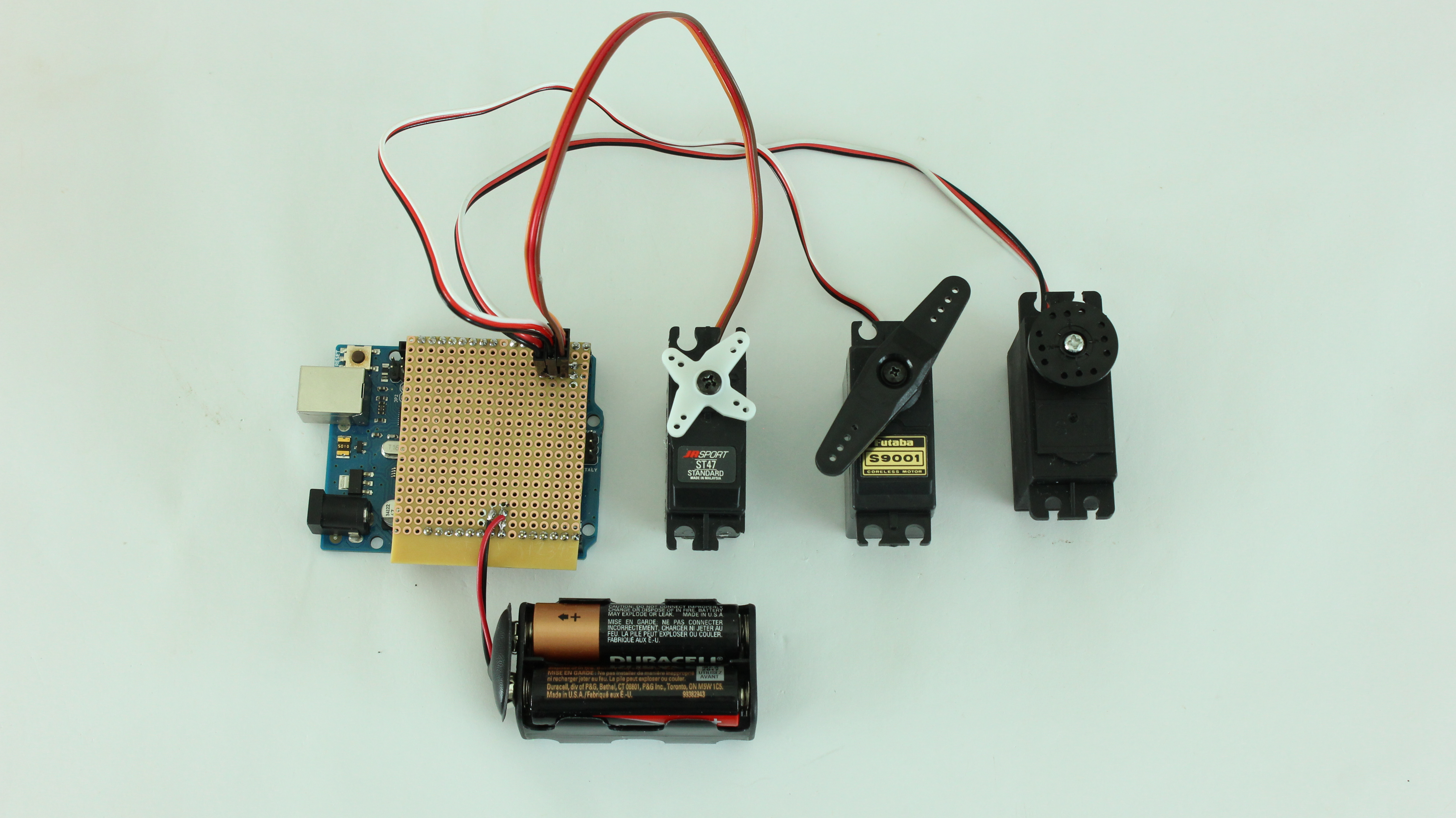
The last kind of shield that we are going to make is a motor speed controller. To build this shield, you will need the following parts:

  • DC Motor
  • NPN Power Transistor
  • Diode
  • 1 kohm Resistor
  • Jumper Wires
  • Battery Connector
  • Screw Terminal Connector
  • LED (optional)
  • 1 kohm Resistor (optional)

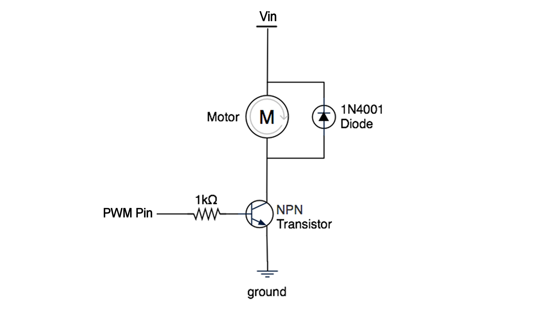
The simplest kind of speed controller uses a Pulse Width Modulation (PWM) signal. This signal can be generated by any of the PWM pins on an Arduino. Unfortunately the digital pins can only output a maximum of 40 mA. This isn’t enough to power most motors. So we need to use an external power source such as a battery pack.

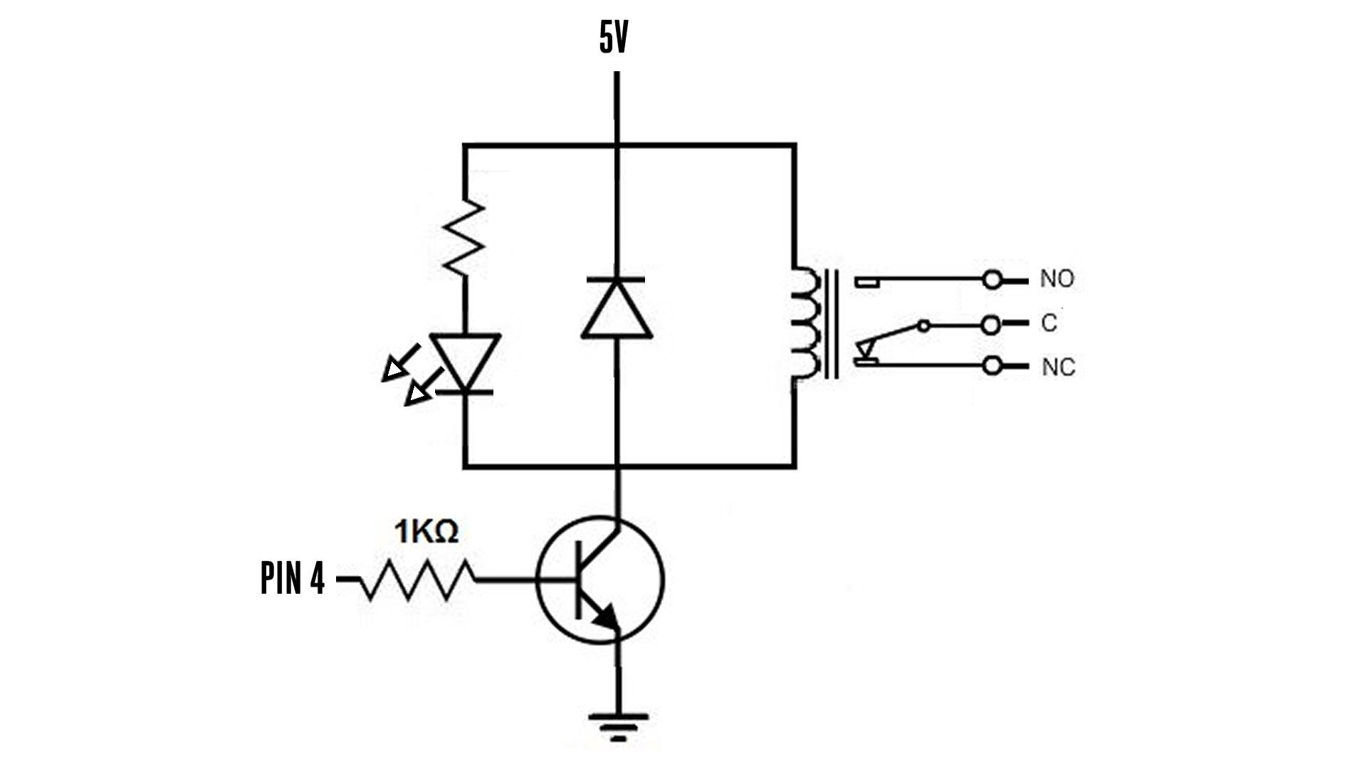
When working with an external power source, you need to use a power transistor. By connecting the PWM pin on the Arduino to the base pin of a NPN transistor, you are able to control the motor with the signal from the Arduino.

In addition to the transistor, you will need to add a resistor to limit the current going to the base pin of the transistor. You will also need to add a diode in parallel with the motor. This will help to protect the Arduino from voltage spike that may occur when the motor turns off.

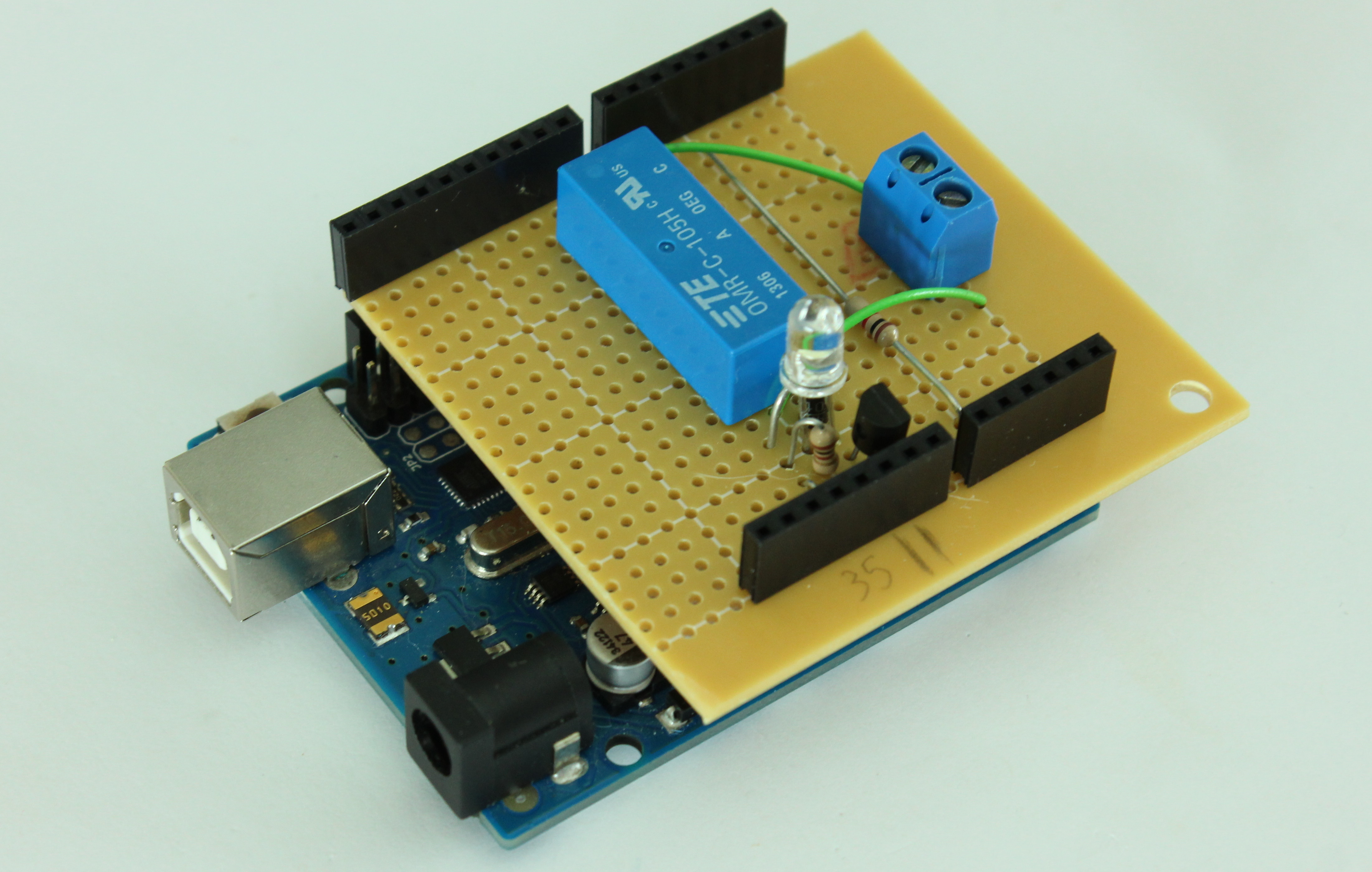
Optionally, you can also add an LED in parallel with the motor to give a visual indication of the speed setting. I included this in my shield.

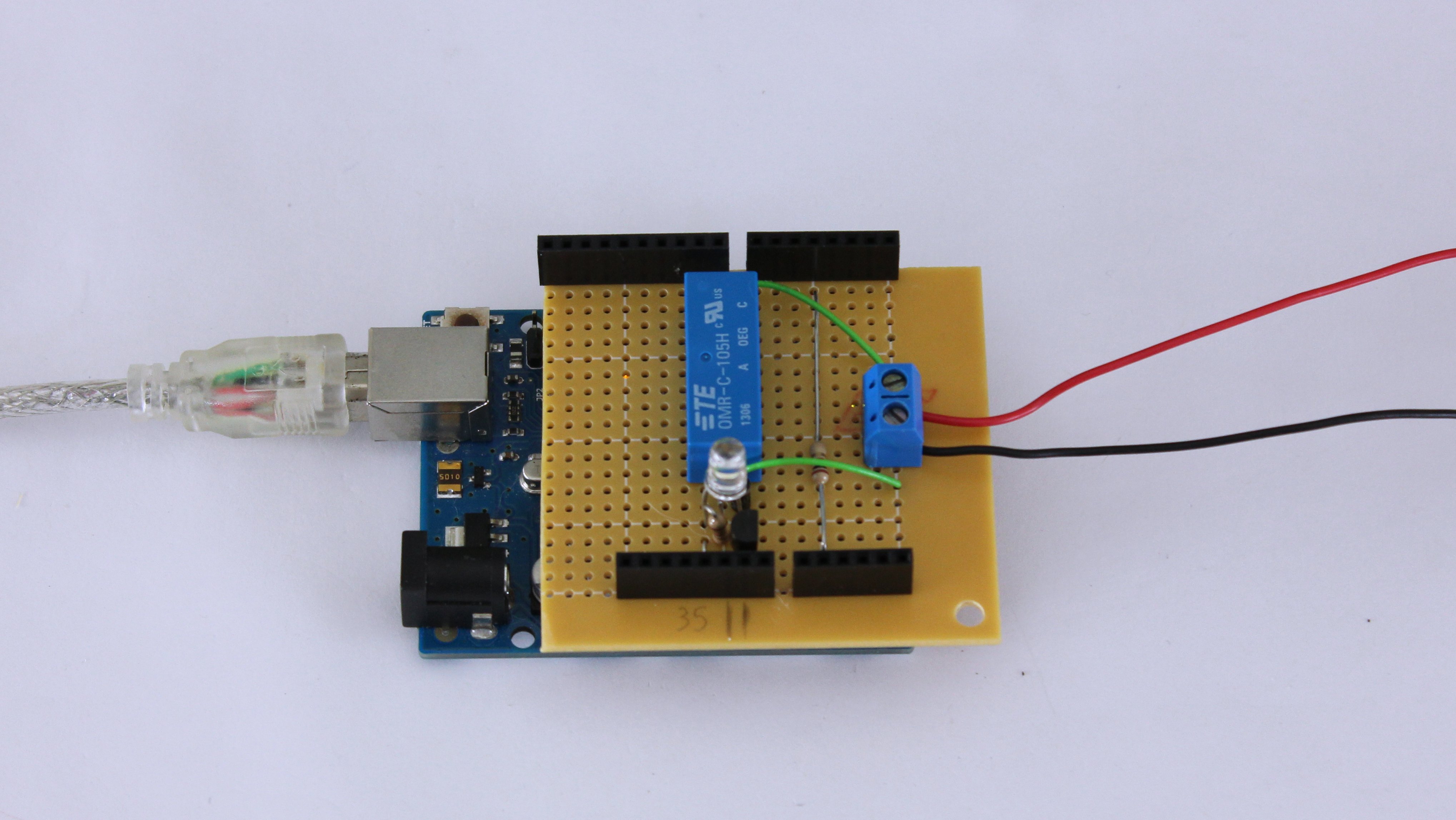
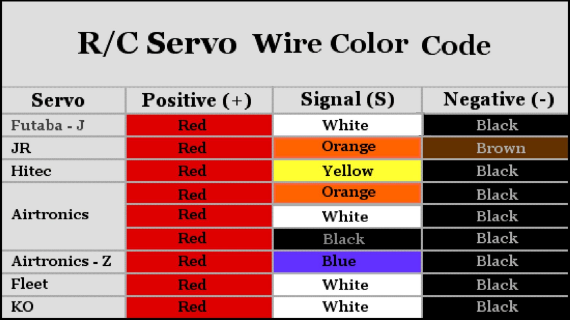
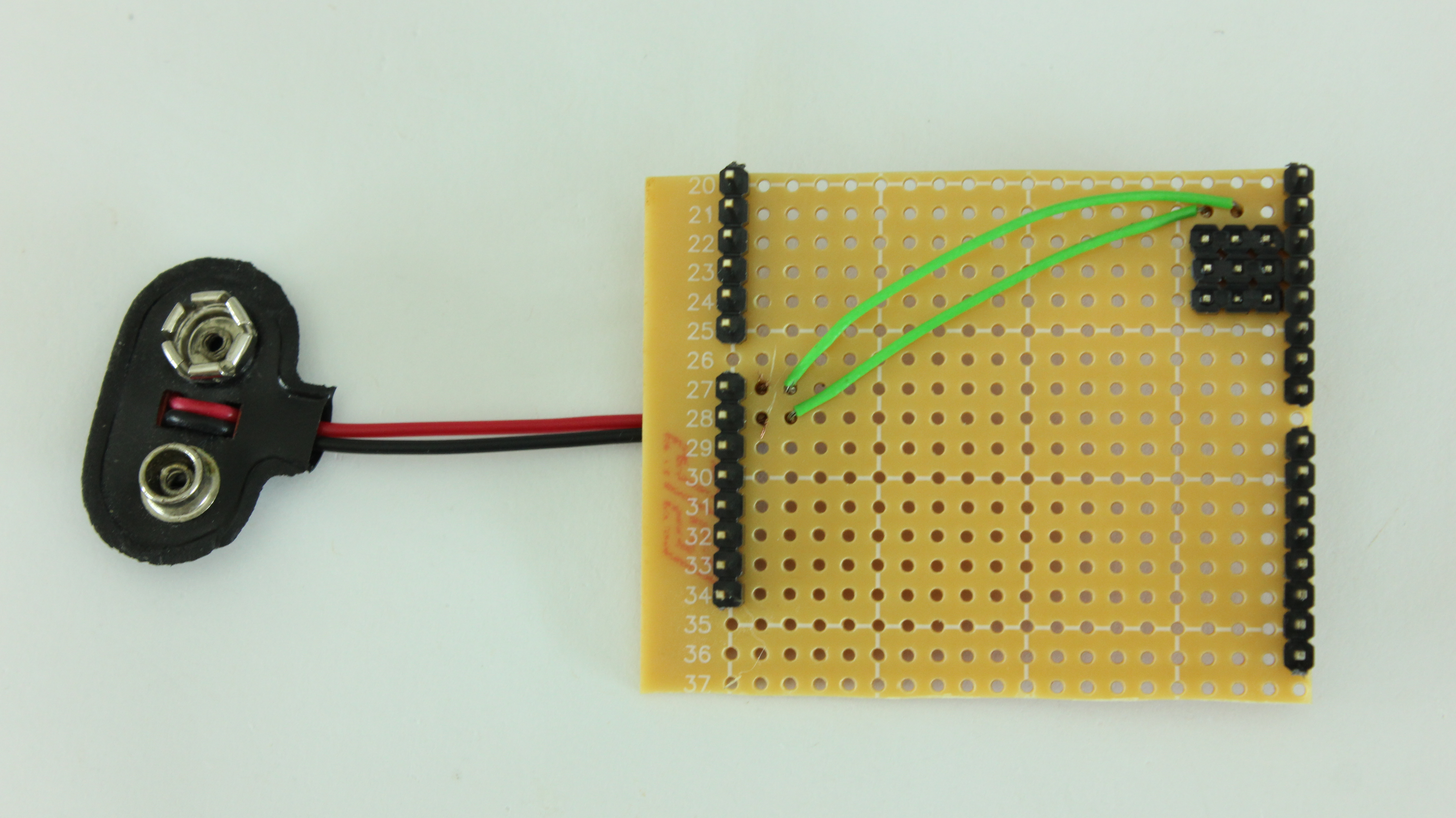
First connect the positive wire from the battery pack connector to the circuit board adjacent to the Vin pin. Then solder the end of the wire to the Vin header pin. Connect the negative wire from the battery connector to the board adjacent to the GND pin and connect the two together.

Next mount the transistor onto the board and connect the emitter pin to the GND pin on the Arduino.

Add a jumper wire to connect these pins to one terminal of a screw connector. Connect the base pin to one of the PWM pins on the Arduino with a 1 kohm resistor. Lastly connect the collector pin to one of the terminals of a screw connector with a jumper wire. Connect the other terminal of the screw connector back to the Vin pin.

If you want to add an LED as a visual indicator, you need to connect it between the PWM pin and GND. Take a resistor and connect one end to the same PWM pin that is connected to the base of the transistor. Connect the other side of the resistor to the anode of an LED. Connect the cathode of the LED to the GND pin.

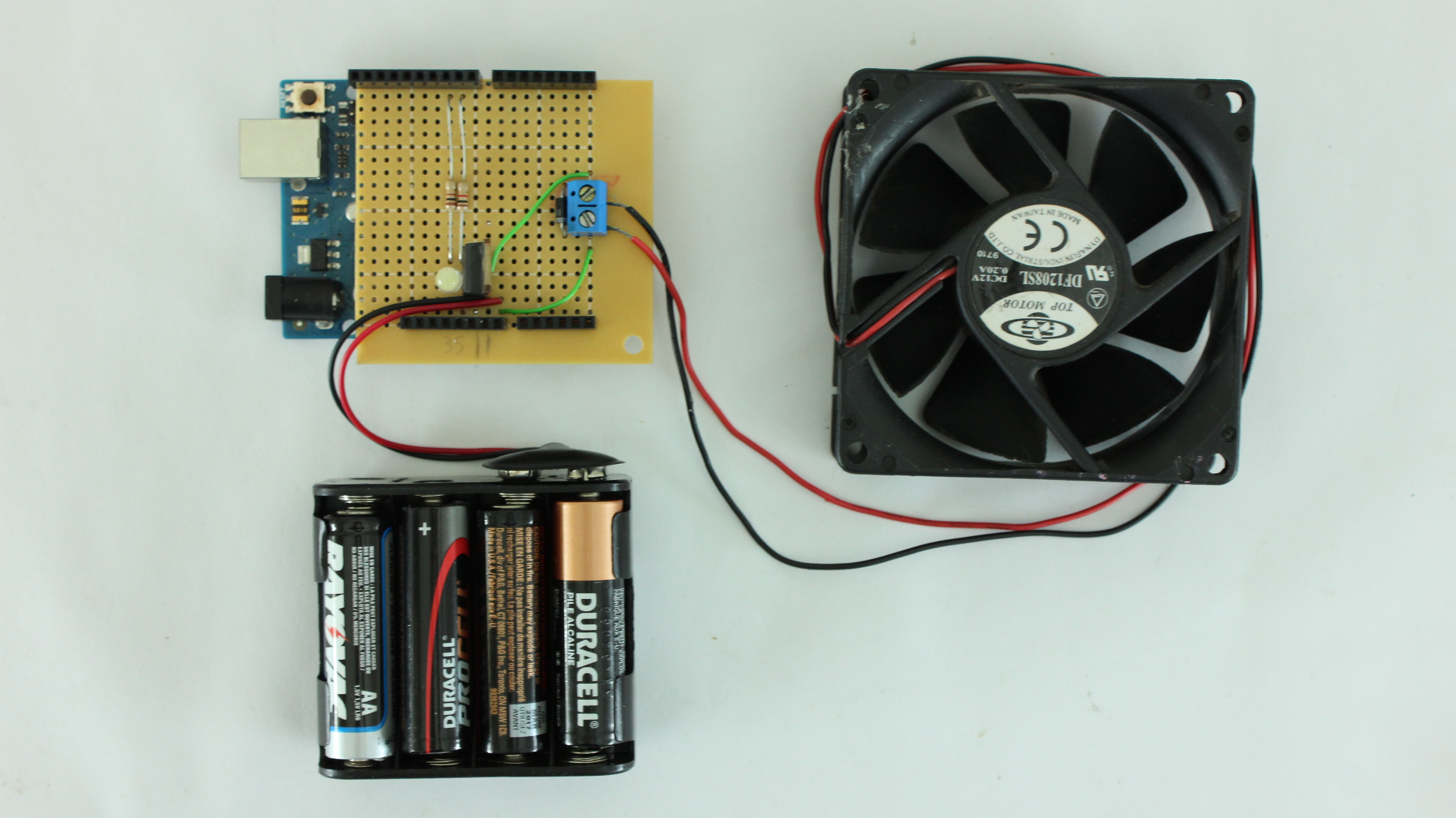
Now your motor speed controller shield is complete. Just connect the motor to the screw connector. Use the analogWrite command to send a PWM signal to the motor and control its speed.