This project describes how to build an audio spy bug with extremely small dimensions that works with a voltage of only 1.5V. This is a tested design and proven to be working reliably when built as described here.
Please note that once built the user is responsible for observing local/national regulations for operating such device!
Depends on the battery used, with the smallest commercially available battery about 48 hours
Range:
The range that can be achieved depends very much on the characteristics of the antenna
With an antenna ¼ wavelength long (e.g. 88cm at 85MHz) the range is approximately 50m in open terrain. The bug is therefore more suitable for surveillance within a building or house
Dimensions:
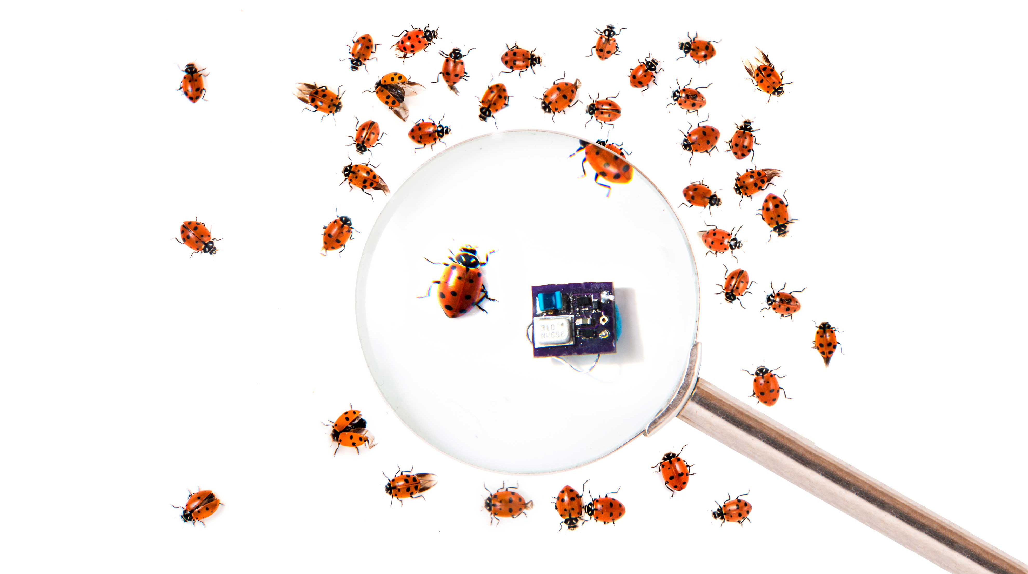
4.75mm×6.8mm (0.187″×0.268″)
For optimal range, the antenna should be at least ¼ of the wavelength. Shorter antennas are possible with certain losses. More information on this later.
The microphone on the left side of the schematic diagram (Figure A) has a maximum voltage rating of 1.45V. The voltage must therefore be brought down to a lower value, since many button cells have a higher nominal voltage than 1.45V. That’s the purpose of the schottky diode D1 which at the extremely low microphone current of approximately 18uA has a voltage drop of only about 150mV. If rechargeable batteries are used, this diode may be omitted and a jumper soldered instead because these batteries often have a nominal voltage of 1.2V.
The microphone output signal is then passed through a 2.2 microFarad capacitor to the base of Q2. This serves to modulate the oscillator frequency. The oscillator comprised of C4, Q1, L1, and C5 oscillates with the here specified values at 81MHz. The oscillation frequency can be adjusted by using different values for C4 and/or L1. Increasing them will lower the oscillation frequency and vice versa.
Figure B. The position of each component is indicated
We will use some of the smallest currently available components on the market. Further miniaturization by different placement of the components would be possible, but makes no sense because the smallest currently commercialized button cell has a diameter of 4.8mm.
At the time of writing this, all of these components are available on the Digikey website. The main website is Digikey.com. Shipping cost may vary depending on where you live. Other suppliers such as Mouser etc. can be chosen too.
In the following part list there are no exact model numbers for resistors and capacitors because they can change over time and are also different depending on the supplier. For the passive components only the capacitance / resistance and of course the overall size are important. Frequency-determining capacitors should be temperature stable types such as NPO. The frequency determining components are chosen here for a frequency of 81MHz. For the coil always select a component with and air core and one that having a high Q factor (Figure B).
Component
Model/Value
Package/Dimensions
MIC
ICS-40310
rectangular 3.35×2.5×0.98mm
D1
BAT54LPS-7
2-XFDFN 1.0 x 0.6mm
C1, C3
100nF ceramic capacitor
01005 0.4 x 0.2mm
C2
2.2uF ceramic capacitor
0402 1.0 x 0.5mm
R1
1MOhm resistor 1/32W
01005 0.4 x 0.2mm
C4
12pF ceramic capacitorNPO
01005 0.4 x 0.2mm
C5
5.6pF ceramic capacitorNPO
01005 0.4 x 0.2mm
L1
220nH inductor, wire wound,
air core (LQW2BASR22J00L)
Below we see the board how it comes from the manufacturer (Figures C and D). They have been panelized and then broken out. We need to remove some material around the edges. The circuit board can probably no longer be produced at home using toner transfer or similar methods because traces are only 0.2mm large and the distance between them is equally small.
Figure C
The provided Gerber files (download them from this link) can be sent to any PCB manufacturer. Best suited for such a small circuit board are companies that put together orders from different customers on a single large board that is then sent to a PCB manufacturer. The cost of each small PCB goes down considerably. An example is Oshpark.com in the US.
Figure D. Here is the other side where the battery will be mounted.
The assembly of the components on the circuit board requires the use of a microscope. First, a little solder paste is deposited on each pad using a needle or a piece of thin wire (Figure E). If accidentally too much is put on the pad it should be removed before soldering.
The board is very lightweight, it should therefore be fixed to a surface before doing the following steps.
Figure E
Then the components are carefully aligned and placed on the pads (Figure F). They can be slightly pushed down to prevent them from slipping when the board is handled.
Figure F
Subsequently, the board has to be heated to about 480° Fahrenheit (about 250 Celsius). This can be done on a hot plate or in a small oven, whatever is available. If an oven is used it should be one without strong air movement, otherwise the parts may simply be blown off the PCB.
The first sign that the correct temperature has almost been reached is the smoke that emanates from the solder paste. The beads of solder then melt at a certain temperature and connect the components to the printed conductors (Figure G). Once this happens, the oven or hot plate should be turned off. When an oven is used, its door should then also be opened.
Figure G
The board should be allowed to cool down a bit before handling. If using a hotplate the board should be removed from the hottest spot in order to avoid damage to the MEMS microphone which is pretty sensitive.
If a button battery is used, a wire can be soldered into the vias connecting the positive battery terminal to the circuit board (Figure H). Of course you can also solder wires to “gnd” and “+” to connect another type of battery.
In this example here 80MHz were chosen deliberately. In many countries, the FM range between 87.5MHz and 108MHz is overcrowded which makes it more difficult to receive the relative weak signal of our transmitter. Even though, in some countries the frequency band reserved for radio stations goes from 76MHz to 88MHz. Many smartphones can therefore be adjusted to use this frequency band instead of the one from 88MHz to 108MHz. This saves us the money we would have to spend for a scanner or a world radio.
The antenna length should be at least ¼ of the wavelength.
Example of a configuration the circuit has been tested with:
C4 in pF
C5 in pF
L1 in nH
Frequency in MHz
Antennalength in cm
Range (open field)
12
5,6
220
81
92 (36″)
160ft
Higher frequencies are also possible.
If a different oscillation frequency is chosen the antenna length should be adjusted accordingly. The wavelength can be calculated according to the following formula::
“λ”is the wavelength, “v” is the speed of light, or about 300000km / s. “f” is the frequency.
The antenna (Figure I) can also be made shorter if you are willing to accept a shorter range. A complete discussion of possible antenna shapes and lengths is beyond the scope of this guide.
Figure I
One possibility is, for example, a short “whip” antenna, that is an antenna which is shorter than a quarter of the wavelength. To compensate for the shorter antenna length, an inductance of a few tens of nH is connected between the antenna wire and the transmitter. The value of this inductor is best determined experimentally.
Instead of the MEMS microphone an electret condenser microphone can also be used. The diode may then be omitted.
If the incoming audio signal is too strong, a resistor may be placed in series with C2. The value of that resistor needs to be determined experimentally.
If low frequency noise like from a fan is present in the room under surveillance the value C2 can be decreased. The circuit works very well with values down to 100nF.
Conclusion
For further questions the author is at your disposal under the following e-mail address: tomtechtod@gmail.com
Please note that once built the user is responsible for observing local / national regulations for operating such device!
Our websites use cookies to improve your browsing experience. Some of these are essential for the basic functionalities of our websites. In addition, we use third-party cookies to help us analyze and understand usage. These will be stored in your browser only with your consent and you have the option to opt-out. Your choice here will be recorded for all Make.co Websites.
Allow Non-Necessary Cookies
Escape to an island of imagination + innovation as Maker Faire Bay Area returns for its 15th iteration!
Buy Tickets today! SAVE 15% and lock-in your preferred date(s).