YouTube player

Sometimes the sun is my friend, warming the house on cool days. Other times it’s my enemy, warming the house on hot days. Blinds are one solution to this problem, but it seems that no matter how I set my blinds before I leave for the day, the weather changes and I come home to a sweltering or freezing house.

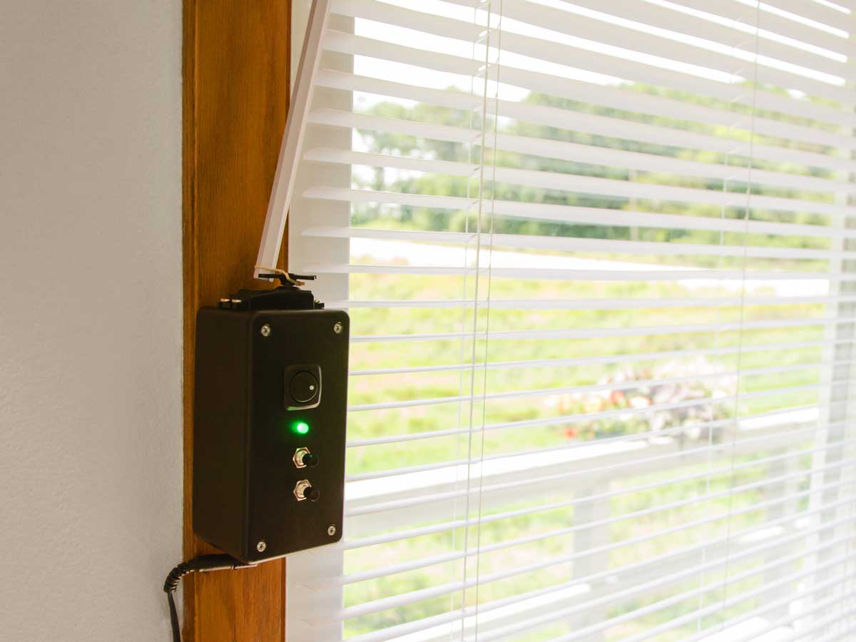
So I built this mini blind minder to open and close them automatically. It’s powered by an Arduino microcontroller, which uses a temperature sensor to read the room temperature and then activates a servomotor to open the slats when it’s too cool and close them when it’s too warm. It has an adjustable thermostat and it can also be operated manually to open or close your blinds with a push of a button.

You’ll solder a custom Arduino “shield” — a circuit board with headers that plug into the Arduino — and then mount it all in a tidy RadioShack project case. This project requires only a moderate amount of soldering, so you can easily build it in a day or a weekend.

blind_minder_complete_c

Project Steps

Prepare the case.

NOTE: All sizes are for the listed components. If you’re using different components, check your measurements before cutting.

Cut a rectangular hole for the servo in the center of the narrow end of the case. There’s not a lot of extra room, so be sure it’s centered. You may need to carve out a bit of the screw posts inside the case for the servo to fit.

Drill four 1/16″ pilot holes for the screws that will secure the servo. (Don’t mount it yet.)

On the opposite end of the case, drill a 5/16″ hole for the power connector and a 1/4″ hole for the temperature sensor.

In the cover, drill one 3/4″ hole for the Manual switch, two 5/16″ holes for the Up and Down buttons, and a 7/32″ hole for the RGB LED.

Wire the off-board components.

Cut sixteen 6″ lengths of hookup wire and strip 1/4″ off each end.

Solder wires to all the leads of the LED, the switches, and the temperature sensor.

Solder wires to the center and edge pins of the power connector.

Add heat-shrink tubing over the soldered connections.

Build the shield.

Cut a piece of perfboard 15 holes by 20 holes. It will just barely fit in the width of the case, so check the fit before going to the next step.

Cut the header pins into blocks of 5, 4, 2, and 2 pins. You should have 3 left over.

Use pliers to push the pins flush with the plastic spacer. This will make the pins long enough to fit securely in the Arduino.

Build the shield (cont'd).

Solder the pins in place on the bottom of the board.

The 5-pin header connects to digital pins 3–7.

The 4-pin header connects to Vin, GND, GND, and 5V.

One 2-pin header connects to A0 and A1.

The other 2-pin header connects to digital pins 8 and 9. Use pliers to bend a dogleg in these pins so they’ll fit the awkward spacing on that side of the Arduino.

Solder the shield.

Refer to the circuit diagram when building the shield.

Solder the following components to the shield and connect them to the appropriate header pins.

  • 10K micro potentiometer. Connect the odd leg to A1, and the other 2 legs to +5 and GND.
  • (3) 100Ω resistors. Connect one each to digital pins 3, 5, and 6.
  • (3) 10K resistors. Connect one end to ground, connect the other near (but not to) digital pins 4, 7, and 8.
  • 3-pin header for the servo. Connect the center pin to digital 9. Connect the other pins to GND and 5V. Mark which pin is the ground so it’s easy to connect the servo correctly.

Calibrate the servo.

Place the shield on the Arduino and connect the servo. Take care to get everything oriented correctly or you could burn out the servo or the Arduino.

Connect the Arduino to your computer with a USB cable.

Download the Mini Blind Minder code as a .zip file here. Unzip the files and open them in the Arduino IDE. (Guidance for setting up the Arduino IDE and connecting to your Arduino can be found here.)

Upload calibrate_servo.ino to the Arduino.

Adjust the screw on the side of the servo until the servo stops turning. This may require a fine touch.

To test the servo, upload test_servo.ino to the Arduino. The servo should oscillate between turning clockwise and counterclockwise, with a 1-second pause between. If not, double check your connections and recalibrate the servo.

Mount the components in the case.

Upload mini_blind_minder.ino to the Arduino.

Disconnect the shield from the Arduino and the servo from the shield.

Attach the servo to the case with its 4 self-threading screws.

Secure the switches and power plug in place with their retaining screws.

Attach the LED with a dab of hot glue.

Hot-glue the temperature sensor in place. The body should stick out the bottom of the case a bit so it can get an accurate temperature reading from the room. (The inside of the case tends to warm up a little bit from the electronics.)

Attach the components to the shield and test.

Solder the switch leads. One lead of each switch connects to 5V. The other leads:

  • The Manual switch connects between pin 4 and the 10KΩ resistor.
  • The Up button connects between pin 7 and the 10KΩ resistor.
  • The Down button connects between pin 8 and the 10KΩ resistor.

Solder the LED leads. In order, starting from the flat edge of the LED, the pins are:

  • Red, connect to the other side of the 100Ω resistor on pin 3.
  • Anode (longest pin) to 5V.
  • Blue to the other side of the 100Ω resistor on pin 6.
  • Green to the other side of the 100Ω resistor on pin 5.

Solder the power connector. The center connector to Vin, the outside connector to GND.

Solder the temperature sensor. From the front (flat side facing you) the pins are, from left to right:

  • +5V. Connect to 5V on the shield.
  • Analog out. Connect to A0 on the shield.
  • Ground. Connect to GND on the shield.

Attach the components to the shield and test (cont'd).

Hot-glue the Arduino into the bottom of the case.

Reconnect the servo and attach the shield to the Arduino. Then plug in the power. After a second or two the light will come on.

Test your Mini Blind Minder, following the “Use it” instructions below to understand how it should operate. If it’s working correctly, proceed to installation.

Install and calibrate.

Lower your blinds and open the slats.

Count how many turns and in what direction it takes to close the slats.

Plug in the power and set it to manual mode.

Adjust the 10K trimpot while alternately pressing the Up and Down buttons. When the trimpot is centered, the servo won’t turn. The further it is from the center, the longer the servo will run when it’s on. Turned clockwise, it will open the blinds clockwise. Turned counterclockwise, it will open them counterclockwise. Adjust the trimpot until pressing the Down button rotates the correct direction and number of rotations to close your slats.

Attach the case to the window frame with 2 wood screws, on the edge away from the window. Position it vertically so that your blinds’ wand fits between the spokes of the servo horn, but doesn’t hit the top of the servo. You can also use double-sided foam tape for a temporary and less durable installation.

Attach the front of the case.

Close the blinds and the slats. Press the Down button to rotate the servo to the closed position. If the light blinks, that means it’s already closed.

Tie a 1/4″ loop in the rubber band and cut off the rest.

Make a simple slip clutch by looping the rubber band around the wand and 2 of the spokes of the servo horn. This will keep the servo from damaging anything in case something goes wrong.

Use it!

When the Manual switch is turned on, the LED turns white and you can open and close the blinds with the press of a button. Pressing the Down button closes them, pressing the Up button opens them. If the light blinks, the slats are already open or closed.

When the Manual switch is off, your Mini Blind Minder is in Automatic mode it will open and close the blinds based on the temperature of the room. The color of the LED shows the current room temperature in relation to the thermostat setting: green when it’s the same temperature, red when the room is hotter than the thermostat setting, blue when it’s colder. Press the Up button to raise the thermostat temperature, Down to lower it. Each press changes the thermostat 1ºC. It can be adjusted between 10ºC (50ºF) and 30ºC (86ºF).

After you adjust the temperature, the Minder may take a few seconds to open or close the blinds.

When it’s powered off, the Minder automatically remembers the thermostat temperature and the position of the blinds.