MonsterBGoneOpenerNEW

M52_Cover_LoRez
Read articles from the magazine right here on Make:. Don’t have a subscription yet? Get one today. On the cover: NASA’s JPL is using VR tech to create the next Mars rover. Illustration by Viktor Koen.

Do you have a child who worries about lurking beasts in his or her bedroom? Are you weary of inspecting closets for fanged creatures? Are your knees sore from examining beneath the bed for clawed critters?

If so, then the Monster-B-Gone is just the solution you need to confirm a fiend-free room for your youngster. Even better, it’s easy for kids to operate, requiring no adult supervision.

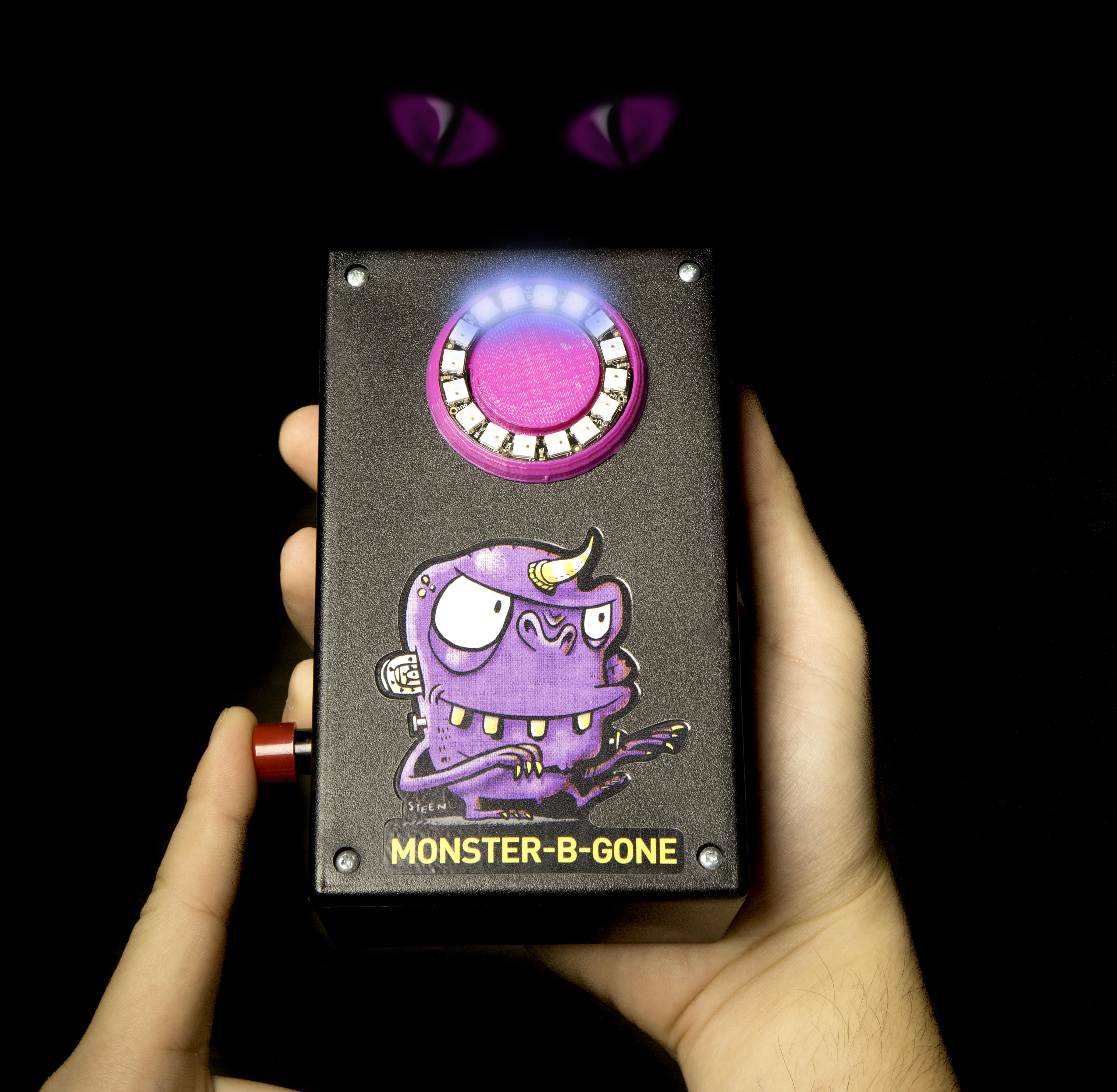
Just push the button — the swirling blue lights let your child know a scan of the surroundings is taking place. Of course, the blue light combines with a beyond-human-hearing ultrasonic wave (um, yeah, that’s it), unpleasant to any monster’s eyes, ears, or antennae. So any monsters within, say, half a mile (800 meters) will immediately disperse and return to their places of origin. When the light turns green, the room is clean.

If you so choose, the Monster Detector will occasionally detect a monster — red alert! — but a subsequent scan will green-light the room again. Whew. Children, sleep tight.

Build Your Monster-B-Gone

The Monster-B-Gone is easy to assemble in a couple of hours, and costs less than $40. Basic soldering skills are required; an understanding of simple circuits and basic electronics is useful, but not necessary if the steps are carefully followed. A drill press or handheld electric drill is needed for part of the assembly.

The NeoPixel LED ring used in this project can be mounted directly on the top of the project box, or you can 3D-print an optional shell for the LED ring. Holes will still need to be drilled through the top, but the shell gives the project a more finished look.

Most of the project’s parts can be purchased from any local electronics supply store, but a few will need to be ordered online. You’ll also need an internet connection to download the free software used for the Monster-B-Gone’s microcontroller (an Adafruit Trinket), and the Monster-B-Gone logo if an adhesive sticker is desired.

Project Steps

1. PREPARE ELECTRONIC COMPONENTS

For easier assembly and disassembly, I typically use a combination of headers and female jumper wires to connect all electronics components. The flexible jumper wires can easily be inserted onto the headers and pulled off during programming and testing. For this reason, the first task I recommend is adding headers to the Trinket, the NeoPixel Ring, and the pushbutton.

The 3×AAA battery box also needs its V+ and GND wires cut and trimmed. You can just solder these trimmed wires directly to their desired locations, but I prefer to add female jumper wire ends onto these exposed wires to make them plug-able too.

P1050214
Figure A. Steps photography by Anthony Lam

The Trinket comes with its own set of headers. Figure A shows the Trinket sitting on top of 10 non-soldered headers. To solder them, I used a small breadboard to hold the headers so the Trinket could be aligned on top.

P1050216
Figure B

Next, add 3 headers to the NeoPixel Ring (Figure B) at the following locations (they’re labeled on the backside): Power 5V DC, Power Signal Ground, and Data Input.

P1050220
Figure C
P1050221
Figure D

Soldering headers to the pushbutton and the battery box wires isn’t required, but I really find them easier to work with during the wiring stage; Figure C shows 2 male headers soldered onto the 2 legs of the pushbutton. Figure D shows the battery wires with female jumpers soldered on. I used some shrink tubing to cover up the solder joint, but electrical tape will work just as well.

P1050223
Figure E

Finally, add a glob of solder to two 3-pin headers to short them (Figure E). These are used to create shared connections for 5V and GND that are needed for both the NeoPixel Ring and the Trinket, as well as a method for plugging the pushbutton into the circuit. You can wrap the solder glob in electrical tape, but leave the longer pins exposed for connecting the jumper wires.

2. 3D-PRINT THE NEOPIXEL SHELL (OPTIONAL)

P1050218

If you have access to a 3D printer, you can print out the mounting shell for the NeoPixel Ring. Download the STL file for the shell here. Figure F shows the shell printed in purple.

3. PREPARE THE PROJECT BOX

P1050230
Figure G
P1050229
Figure H

You’ll need to drill a few holes in the project box. Carefully place the NeoPixel Ring (with headers) on the project box lid and make 3 small marks where the headers touch the lid. Drill a ¼” hole at each mark, then test-fit the NeoPixel Ring (and shell, if you’re using it) and ensure the headers fit into the drilled holes (Figures G and H).

If the headers can be reached from beneath the lid, glue the shell to the project box lid and set the NeoPixel Ring aside until final assembly. (If the headers can’t be reached, you may need to drill the holes a little larger.)

P1050225

Next, decide where to place your pushbutton. I drilled a ½” hole in the left side of the project box (Figure I), but it could easily be mounted on the box lid beneath the location of the NeoPixel Ring.

4. PROGRAM THE TRINKET

To program your Trinket, first you must install the latest Arduino development environment (IDE), version 1.6.9 at the time of this writing, and update it to recognize the Trinket. Adafruit has detailed instructions for this task here. Be sure to follow those steps related to your specific operating system (Mac or Windows); Windows users will also need to download special Trinket drivers.

Once you’ve got your Trinket blinking using the Flash test program, you’re in good shape. All you need to do now is replace the Flash sketch (program) with the modified Monster-B-Gone sketch. Download the file MonsterBGone.ino, open it in the Arduino IDE, then hit the Upload button to load it onto the Trinket.

5. ASSEMBLY

Figure 11

Before you assemble the Monster-B-Gone in the project box, I highly recommend wiring everything up outside the box and testing first. Pay careful attention to the wiring; one misplaced wire could result in a damaged Trinket or NeoPixel LED, so double-check all your connections against the wiring diagram (Figure J).

Once everything is wired up, flip the battery box switch to the On position (after inserting the batteries, of course) and press and hold the push button (it takes a few seconds for the Trinket to boot up). You should see a short animation of spinning blue lights, followed by the all-green “coast is clear” lights.

If you’re not seeing any animation, you’ll want to check all your wiring again. If the Trinket is powering up (a solid green-yellow LED stays lit when it’s powered) but the NeoPixel animation isn’t playing, you’ve likely got a wire connected to the Trinket incorrectly. Verify the Data Input header on the NeoPixel Ring is connected to pin 0 on the Trinket. If you’re still not seeing any animation, verify you’ve uploaded the MonsterBGone sketch to the Trinket.

P1050268
Figure K

Once you’ve got the animation playing on the NeoPixel Ring, it’s time to pull everything apart and reassemble inside the project box (Figure K). Wire everything up as before and use velcro or double-sided tape to secure the battery box inside the project box. You might also want to use a dab of hot glue (in place of tape) to secure the Trinket to one of the inner walls as well. Use the project box’s screws to secure the lid in place.

6. FINISHING TOUCHES

I created my own graphics for the top and sides and had a local print shop print them for me on a vinyl sticker sheet. Then Make: illustrator Brandon Steen came up with the awesome purple monster design you see here. You can download the monster graphic from here.

Illustration by Brandon Steen

UPGRADES

Where to go from here? An obvious choice would be to add a sound effect. One easy way would be to use an inexpensive sound recording module (such as RadioShack #2761323). Drill some tiny holes in the project box, hot-glue the speaker in place, and wire the module’s Play button directly to the Monster-B-Gone pushbutton so it triggers your sound effect.

And I’ve always liked the moving arms on the “P.K.E. Meter” in the movie Ghostbusters — a couple small servos could be easily added, one per side, with holes drilled into the project box for the shafts. Create an eye-catching “antenna” for each motor and you’ve got sound, lights, and motion.

I hope you like the Monster-B-Gone. Even better, I hope some children will find peace at night when their parents introduce them to this useful device. Imagination is a powerful thing, and giving a child a tool (and letting them help you make it!) to help combat an imaginary monster can turn a parent into an instant hero. Have fun!

Customize Your Monster Scan Animation!

The Monster-B-Gone sketch is a modified version of the Kaleidoscope Goggles sketch created by Adafruit. You can easily open the sketch in the Arduino IDE and experiment with different colors, patterns, and timing! To adjust the behavior of the LEDs, just change the following values, found near the top of the source code, then upload your new version to the Trinket.

SCAN TIME

By default, the “searching” spinner will be blue for a random duration between 5 and 8 seconds, then will always change to solid green. Lines 11 and 12 can be adjusted to make this duration longer or shorter. Setting these to the same value will effectively fix the duration.

11: #define MIN_SEARCH   5   // min possible search animation (secs)
12: #define MAX_SEARCH   8  // max possible search animation (secs)

FINDING MONSTERS!

Line 13 sets the probability of “finding monsters,” which will cause a bright, solid red instead of green when the animation finishes. To avoid terrifying children, this is set to a default of 0. Setting it to 50 would cause monsters to be found half the time.


13: #define MONSTER_PCT  0  // chance of finding monsters (percent [0-100])

CUSTOMIZE COLORS

Lines 15 through 17 define the colors for each state. These are RGB hex values similar to HTML/web colors, but do note that the order is GRB (green-red-blue), so 0xff0000 is green rather than red. You can find HTML color tables online and experiment with customizing all 3 colors.


15: #define COLOR_SEARCH 0x0000ff  // color of search spinner (GGRRBB hex)
16: #define COLOR_OKAY   0xff0000   // color indicating NO MONSTERS (GGRRBB hex)
17: #define COLOR_NOTOK  0x00ff00  // color indicating MONSTER FOUND (GGRRBB hex)

SPINNER ANIMATION

Lines 19 through 21 adjust various aspects of the spinner such as its rotational speed and how long the “taper” of the spinner extends across the ring. Note that the speed values here are in milliseconds, so 1000 would be one second. Fool around with these for your own custom animation style.

19: #define SPIN_SPEED   128   // search animation speed (ms)
20: #define SPIN_DELAY   20    // timing delay (ms)
21: #define TAIL_LENGTH  33    // length of tail of total ring (percent [0-100])