I was playing around with a Picaxe microcontroller one day, trying to make a little keyboard. I wanted to build an absolutely minimal hardware frame that I could put together quickly without a circuit board. The result was the MoofTronic — a small electronic instrument built on a 24-pin IC socket. To play 8 different notes (1 octave in the key of C) against a fast-modulation drone, you touch a stylus to 8 legs of the socket. It also has a small antenna that you can touch to add an effect to the note being played. The 8-pin Picaxe microcontroller that runs the software and generates the sounds sits in one end of the socket and has a small speaker mounted on top. A programming port allows you to easily debug and test new sound-making programs.

Project Steps

Fit the 8 resistors to the IC socket bottom.

The 8 resistors form a ladder of increasing resistance that allows the socket pins to play different notes. Start the ladder by bending the legs of the 1K resistor around pins 12 and 13, leaving enough wire on one end to join pin 13 to pin 14.

Trim excess wire and repeat down the socket, joining pin pairs with the 2.2K, 3.3K, 4.7K, 12K, 22K, 33K, and 39K resistors, in order. No jumper is needed between pins 20 and 21. Finally, solder the resistors in place. Download the schematics PDF under Files above.

Add the voltage regulator.

Trim pin 3 of the 78L05 voltage regulator to about 1/8″, then solder it to the red wire of the battery clip and cover the joint with heat-shrink tubing.

With the 78L05 facing up, bend pins 1 and 2 out at right angles, pin 1 to the left and pin 2 to the right. Positioning the regulator flat within the socket, bend pin 1 around the IC socket’s pin 1 and bend the regulator’s pin 2 around the socket’s pin 24. Trim the wires, but don’t solder yet.

Wire the link and 10K resistor.

Solder a wire diagonally from pin 1 to pin 20 of the IC socket. Connect pin 22 to pin 24 with a 10K resistor. Wrap the legs around the pins, but don’t solder yet.

Add the stylus and antenna.

To make the stylus, strip and tin a 5″ length of wire and fit some heat-shrink over one end, leaving a bit of metal exposed. Solder the other end to pin 22 on the socket.

For the antenna, solder some leftover wire from a resistor leg to pin 3 of the socket, and bend it around to the top.

Add the program port.

Cut three 4″ lengths of wire and solder 1 wire each to socket pins 2, 23, and 24. Cut the wire from pin 2 in half, and solder-splice a 22K resistor in the middle. Cover the resistor with heat-shrink.

Solder the wire from the 22K resistor to the ring (middle) contact of the 3.5mm audio jack, solder the pin 24 wire to the jack’s tip contact, and solder the pin 23 lead to the sleeve (inner) contact.

Solder a 10K resistor between the tip and ring contacts of the audio jack, and reinforce the connections with 3/8″ heat-shrink. Finally, bundle the programming port and battery clip leads together with 2 cable ties.

Fit the Picaxe microcontroller.

Fit the Picaxe-08M into the 24-pin IC socket. Pin 1 on the Picaxe goes to pin 1 of the IC socket.

Note: I used a 12.7mm (0.5″) wide socket, so I had to bend the Picaxe pins slightly. If you use a 10.16mm (0.4″) wide IC socket, you don’t have to bend the IC socket pins, but it’s a bit harder to fit the resistors.

Add the speaker.

I used an old in-ear headphone speaker, so the first thing was to disengage it from the surrounding plastic. Glue the speaker onto the Picaxe, and add a bit more glue where its delicate little wires attach to the speaker coil.

Cut the speaker wires to about 1″ and solder one to socket pin 24 and the other to pin 21. Solder the black (–) battery wire to socket pin 24, and reinforce the socket ends of the headphone wires with more glue.

Program the microcontroller.

Download and install the Picaxe Programming Editor software, free from http://www.rev-ed.co.uk/picaxe.

Then download the mooftronic.bas program file from http://www.makezine.com/15/mooftronic.

Connect the serial cable from the computer to the programming port on the MoofTronic. Launch the Picaxe Programming Editor. Select File —> Open, then open the file mooftronic.bas from the folder you downloaded it into.

Power up the MoofTronic by connecting the 9V battery. Now load the program onto the MoofTronic by clicking Picaxe —> Run. You’ll see a dialog box with a progress bar while the program is loading. This takes only a few seconds. Then a second dialog box will tell you that you have successfully programmed the Picaxe.

Test and glue.

Fit the 9V battery into the battery clip, and test that the device works. Start making noise with the MoofTronic by touching any pin from 5 to 12 of the IC socket with the stylus. If you also touch the small antenna with your finger, the pitch of the sound changes, and quickly goes up and down.

Once it’s all working correctly, fill the bottom section of the IC socket with glue from the hot glue gun. This stabilizes all the little wires and keeps them from breaking off.

Go nuts.

One of the best things about the MoofTronic is that the software can easily be changed, reprogrammed, and tested on the hardware in a matter of minutes. So once you’ve built the hardware, go crazy hacking some new sounds!

Conclusion

This project originally appeared in MAKE Magazine Volume 15.

Related posts on Make: Online:

Hand-held Noiseboxes Sound Smoothe

http://blog.makezine.com/archive/2008/12...

Weekend Project: 
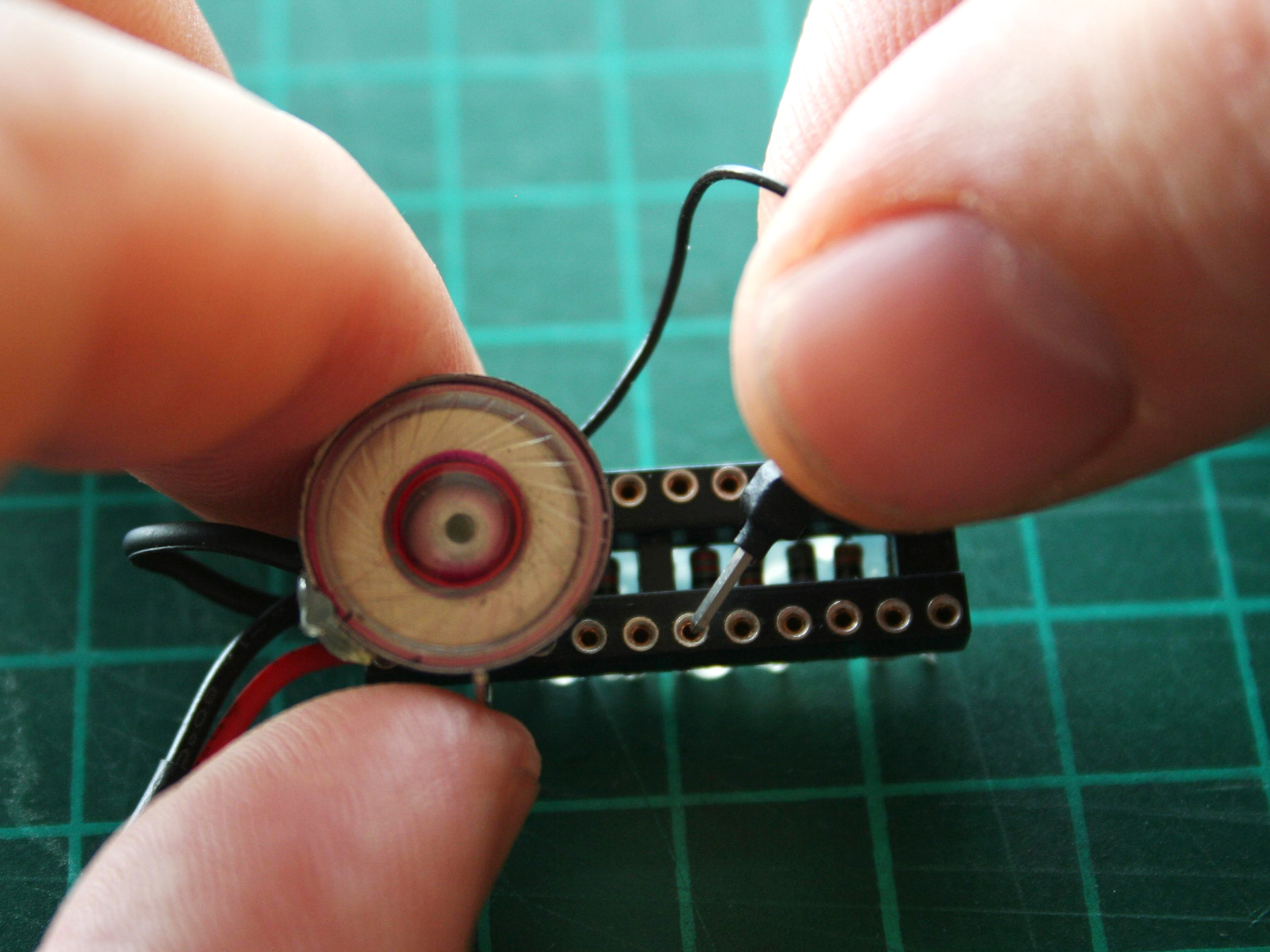
MoofTronic Mini Synth

http://http://blog.makezine.com/archive/2009/05...