YouTube player

A transistor is an electrical component that functions, most basically, as a switch — in principle not so different from a light switch. Instead of a physical movement, however, a transistor is controlled by a flow of electricity. And unlike your basic light switch, a transistor can be on, off, or somewhere in between.

Most transistors have three connections: one for current in, one for current out, and one that controls the “switch.” The current flowing through a transistor can be larger than the current controlling it, so it can become an amplifier: Connect the input to a power source (like a battery), and the control lead to a weak signal (like a guitar pickup), and the output will sound like the control signal, only louder. Just how much louder depends on a lot of things, but a factor of 200 is routine. This number is called gain.

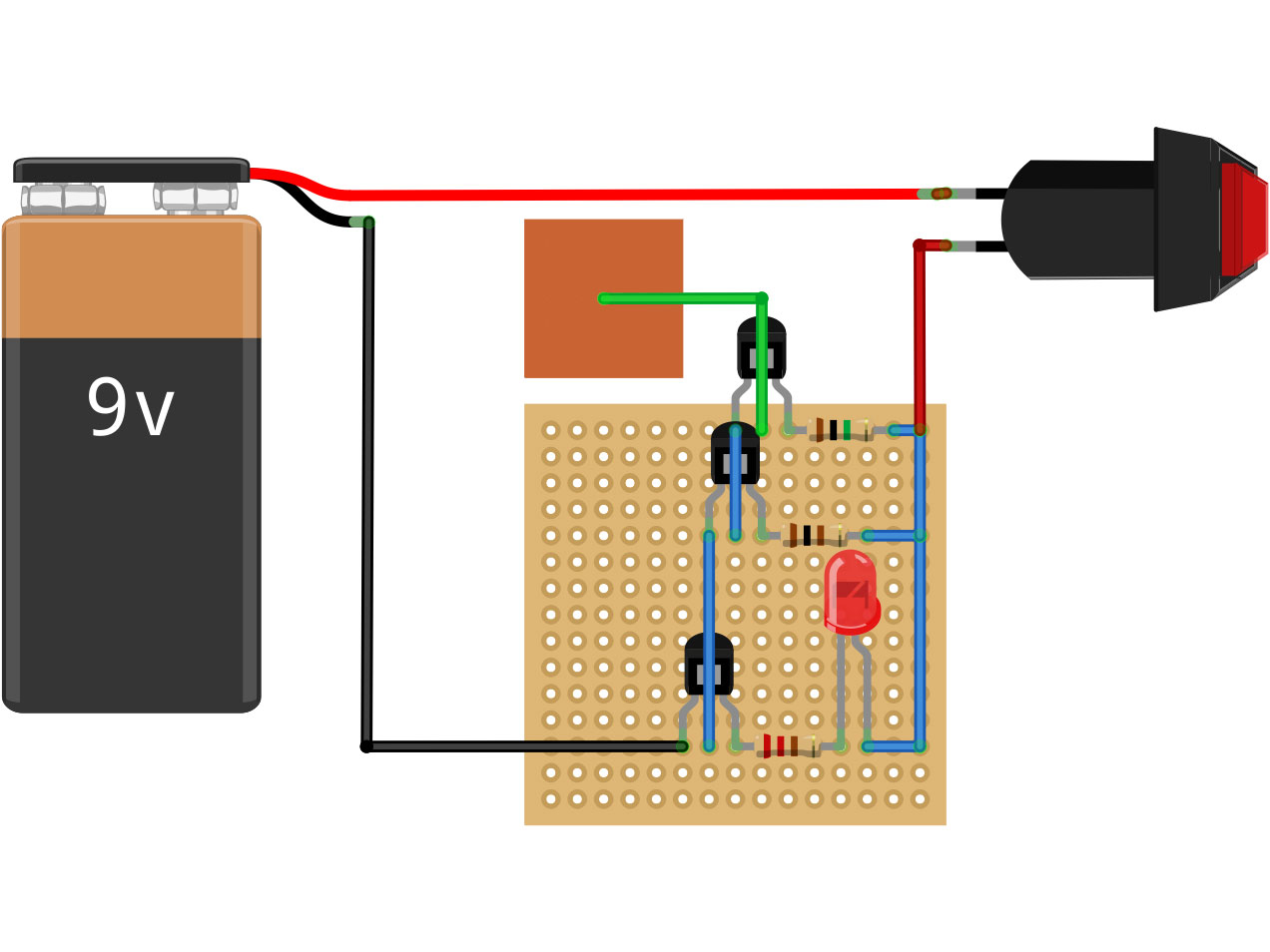
fritzing_rework_perfboard
fritzing_rework_schematic

If you use the output from one transistor to control another, the gains multiply. With two transistors, the ideal gain becomes 200 × 200 = 40,000, and with three transistors (as in this circuit), 200 × 200 × 200 = 8,000,000! That huge gain lets you use it to detect the tiniest movements of electricity — even those created at a distance by induction or static charge!

NCVD_STEP12-1

What will the next generation of Make: look like? We’re inviting you to shape the future by investing in Make:. By becoming an investor, you help decide what’s next. The future of Make: is in your hands. Learn More.

Project Steps

Prepare the Perf Board

Trim down this perf board so it is 15 holes wide and 7 holes tall. Mark your line and either score-and-snap the perf board or use a rotary tool to trim the perf board down to size.

Also trim off the corners of the perf board (image 3). This will ensure the lid of the enclosure will close (Step 14).

Label the Perf Board, Insert the Transistors

Label the perf board with rows 1-7. Also label the columns. While we won’t use all of the columns of this perf board design, I’ve gone ahead and labeled columns C-M accordingly.

Transistors have three leads and each perform different functions electronically. This determines how they are installed in a circuit.

Place a transistor on your work surface with the curved side of the transistor package at rest; you should be looking at the flat side of the transistor, which has some labelling on it. The 2N3904 leads should be pointing towards you. The leads from left to right are: Emitter, Base, Collector.

Insert the first 2N3904 transistor so its emitter is in L3, base is in L4, and collector is in L5.

Insert the second 2N3904 transistor so its oriented in the same manner, occupying the J column: emitter in J2, base in J3, and collector in J4.

Insert the final 2N3904 transistor so it occupies the H column: emitter in H1, base in H2, and collector in H3.

Solder & Bend the Transistors

Solder all the leads of the transistors, but do not clip the leads.

Now for some clever connections using the transistor leads.

Bend the transistor leads so that the L3 emitter is touching the J3 base and the J2 emitter is touching the H2 base. Double-check to ensure you’ve bent the correct leads. Solder those two transistor-to-transistor connections (image 3).

Bend the transistor base at L4 so it extends away from the components on the perf board (image 3)

Bend the transistor emitter at H1 so it extends in the same direction as the the L column transistor (image 3).

Insert and Solder the Resistors

Insert the 220Ω resistor (red, red, brown) into coordinates H4 and E5. Bend the lead occupying H4 so it touches the collector at H3. Solder the two components together and also solder the resistor lead to the board at E5. Trim the leads at H3-H4 but do not clip the E5 lead yet.

Insert the 100kΩ resistor (brown, black, yellow) into coordinates J5 and G6. Bend the lead occupying J5 so it touches the collector at J4. Solder the two components together and also solder the resistor lead at G6. Trim the leads at J4-J5 but do not clip the G6 lead yet.

Insert the 1MΩ resistor (brown, black, green) into coordinates L6 and I7. Bend the lead occupying L6 so it touches the collector at L5. Solder the two components together and also solder the resistor lead at I7. Trim the leads at L5-L6 but do not clip the I7 lead yet.

Wire the LED

Cut two 4″ lengths of red and black wire and strip 1/4″ from each end. Tin the wires with a bit of solder.

Trim down the leads on the red LED. Trim the short leg (cathode) first, so you don’t forget which leg should be shorter. Then trim the long leg. Your LED should look like the LED in image 1.

Connect the red wire to the positive LED lead, and the black wire to the negative lead.

It’s a good idea to use heat-shrink tubing to prevent shorting. Slip a short length of tubing over the two soldered LED leads and shrink with heat (image 3).

Back at the perf board: thread the black LED wire through E6 and solder the wire so it connects to the E5 resistor lead.

Thread the red LED wire through E7 and solder it to the board pad. Bend the resistor leads from G6 and I7 to E7. Solder those connections. (See this image for clarity on this connection.) Trim the excess leads.

Connect one wire from the push button switch

Cut one 3″ length of black wire, strip, and tin the ends.

Solder one end of the black wire to the push button switch. Slide a piece of heat shrink tubing over the black wire solder connection and shrink with heat (image 2).

Solder the other end of the black wire to the perf board at H7. Solder the wire first to the perf board pad, then solder a connection to the resistor lead spanning from I7->E7. See image 3 for clarification.

Finish wiring the switch and battery clip

Tin the red wire from the 9V battery clip. Slide a piece of heat shrink tubing over the red wire. Solder the wire to the available lead on the push button switch. Slide the heat shrink tubing over the soldered connection and shrink with heat (image 2).

Tin and solder the black wire of the 9V battery clip to I1 and also solder it to the transistor emitter at H1.

Prepare the copper pad wire

Cut, strip, and tin a short piece of green 22AWG wire approximately 1 1/2″ long.

Solder one end of the green wire to M4 and bridge the wire to the transistor base at L4.

All the solder connections on this perf board are now complete! Check your perf board for any unintentional connections. Trim and clean any remaining leads from the underside of the perf board.

Prepare the enclosure cover

Two holes will be drilled in the enclosure cover for the LED holder and the momentary push button switch. Because the battery will occupy most of the enclosure’s interior, you will want to accurately locate the drill holes for these two components.

Place a piece of masking tape just below the lid’s screw holes. It does not matter which end of the lid you place the masking tape on.

With the masking tape end of the lid facing you, place the nut from the push button switch on the left and the LED holder on the right, just below the lid’s screw holes. Mark their approximate center.

Note which mark is for which component, because the hole sizes will be different.

Drill the enclosure lid holes and mount push button

Carefully drill out the holes for the LED holder and push button. Use a 1/4″ drill bit for the LED holder hole (image 1) and a 5/16″ drill bit for the push button hole (image 2).

Remove the button plastic from the switch. Thread off the washer nut and place aside. Insert the switch from the underside of the enclosure lid into the 5/16″ hole (on the right in image 3). Thread the washer nut back on top of the switch and tighten with a pair of pliers (image 3). Re-install the button plastic on top of the switch (not shown in Step 11 images).

Remove the button plastic from the switch and insert the switch into the second hole. If it doesn’t quite fit, use a small knife or a file to make the hole a bit larger.

Mount the LED holder and LED

Insert the LED holder into the 1/4″ hole from the top side of the enclosure lid.

Working from the bottom side of the enclosure lid, insert the LED into the holder.

Cut & mount the copper strip

Cut a 3/4″ x 1 1/2″ piece of copper clad PCB material from the sheet with a rotary tool or hack saw blade.

Apply a small piece of double-sided foam tape to the back of the copper and stick it on one end of the plastic enclosure box.

Drill hole for green wire and solder to pad

Carefully drill a 1/16″ hole through the copper and plastic case near the center of the copper strip.

Slot the perf board circuit in between the enclosure’s interior screw mounts. It will fit snug. The underside of the perf board will face the open interior of the enclosure (where the battery will eventually be placed).

Thread the green 22AWG wire from the perf board through the hole so that it pokes through to the outside (image 2). Bend the wire over and solder it to the copper (image 3).

Note: If soldering to the copper doesn’t work, score the copper with a file or a bit of sandpaper.

Put everything into the enclosure

Now that everything is soldered together it will take some patience to fit all the parts into the enclosure.

Connect the 9V battery to the connector and lower it between the screw mounts.

Route excess wire length and gently close the lid. Once satisfied, screw the lid into place.

Usage

Warning: Experiment and have fun but never ever touch the copper strip to a bare wire that has live voltage!

Hold the non-contact voltage detector near a live AC power line and depress the button: it will light up. The detector can be a little sensitive about the position it’s held in so if the LED doesn’t light up, try moving the detector around a little, while keeping the copper strip close to the wire.

It’s also fun to see how it detects static electricity. Try quickly rubbing your hand across some carpet several times then hold your hand near the copper strip. The LED should light up brightly from the static charge build up.