000 Title

MAKE contributing writer Alastair Bland first introduced us to this simple, effective circuit back in 2009. It takes higher-voltage alternating current (AC) from a retro-style bike headlight generator, converts it to direct current (DC), and steps it down to a safe voltage for charging your cell phone or other mobile device.

You may have one of these old bike generators lying around.  If not, they can still be bought new or used online and in some retail bike shops. Technically, this device is an alternator, a very simple and reliable generator that turns rotational momentum into AC electricity.

The phone charger circuit consists of a rectifier, a capacitor, and a voltage regulator.  The rectifier contains four one-way electrical gates called diodes which, working together, convert the back-and-forth wiggling of the charges in AC to a series of DC charge pulses.

The large capacitor connected between the DC terminals of the rectifier smooths out these pulses, charging up when there’s more energy in the system and discharging when there’s less.

Finally, the voltage regulator holds the incoming DC power down at a steady 5V, which is what most cell phones and other mobile devices are designed to accept.  Without the regulator in place, the phone charger might deliver more than 5V to your device, which could damage it.

YouTube player

Project Steps

Prep the box.

Drill a centered 1/4″ hole in each end of the box, and another in the lid.

Install a 1/4″ grommet in each of the holes you just drilled.

Mount a large broom clip on the outside of the lid using a 6-32 x 1/2″ machine screw secured with a 6-32 hex nut, a #8 split washer, and a #8 flat washer inside the lid.

Prep the voltage regulator.

Bend the LM7805’s center (ground) lead down 90 degrees, and its lefthand (input) lead up 90 degrees, as shown.

Cut two 2″ jumpers from 22 AWG solid core hookup wire–one red and one black. Strip about 1 cm of insulation from each end of each jumper. Solder one end of the red jumper to the regulator’s input lead, and one end of the black jumper to its ground lead.

Trim the excess input and ground lead away from the voltage regulator with a pair of wire cutters.

Install the voltage regulator.

Secure the LM7805 in one corner of the box by driving a #6 x 1/4″ sheet metal screw through the hole in the regulator’s back plate and into one of the box’s molded-in mounting holes.

Slip an insulated 22-16 AWG #6 ring-tongue lug over the regulator’s righthand (output) lead, and secure to the adjacent mounting hole using a second #6 x 1/4″ sheet metal screw.

Crimp the ring-tongue lug to the regulator lead with electrician’s pliers.

Prep the rectifier.

The rectifier’s positive DC output lead will be indicated with a small + sign on top of the case. The negative DC output lead may or may not be marked, but it will always be directly opposite. Bend the DC output leads up along the sides of the rectifier case as shown.

Bend the capacitor leads directly away from each other as shown.

The capacitor’s negative lead is marked on the side of the case. Making sure the polarities match–positive to positive and negative to negative–stack the capacitor on top of the rectifier and twist the leads together as shown.

Connect rectifier and regulator.

Bend the twisted leads up along the sides of the capacitor case, as shown.

Solder the free end of the black jumper to the negative side of the capacitor/rectifier combo.

Push the capacitor/rectifier combo down into the box and solder the free end of the red jumper to the positive leads, as shown.

Mount the rectifier.

Loosely secure a bare 22-16 AWG #6 ring-tongue lug to each of the two remaining mounting holes using a #6 x 1/4″ sheet metal screw. The lugs should be free to rotate and tilt up and down.

Thread the rectifier’s AC input leads into the bare ring-tongue lugs and bend the excess straight up, as shown. Tighten down the sheet metal screws to firmly secure the lugs in place.

Use electrician’s pliers to crimp the lugs to the rectifier leads. Trim away the excess from each lead with wire cutters.

Connect external wiring.

Cut the adaptaplug cable in half and thread the ends into the box through the grommets at each end. Tie a strain-relief knot inside the box about 3″ from each end.

Separate about the leads from each end of the cable over a distance of about 1-1/2″. Strip about 1 cm from each end of each lead, and securely crimp an insulated 22-16 AWG #6 ring-tongue lug to the bare wire.

One at a time, remove and reinstall the sheet metal screws from the mounting holes in the box, securing the ring tongue lugs from the adaptaplug cable as shown. The polarity on the rectifier side does not matter; on the regulator side, make sure the lead with the white stripe is connected to the positive output, as shown.

Attach the box to the bike.

Connect the adaptaplug micro-USB adapter to the DC / voltage regulator side of the adaptaplug cable. Make sure the adapter’s + sign is aligned with the word “TIP” on the plug socket, as shown.

Install the lid on the project box and secure with the four bundled case screws.

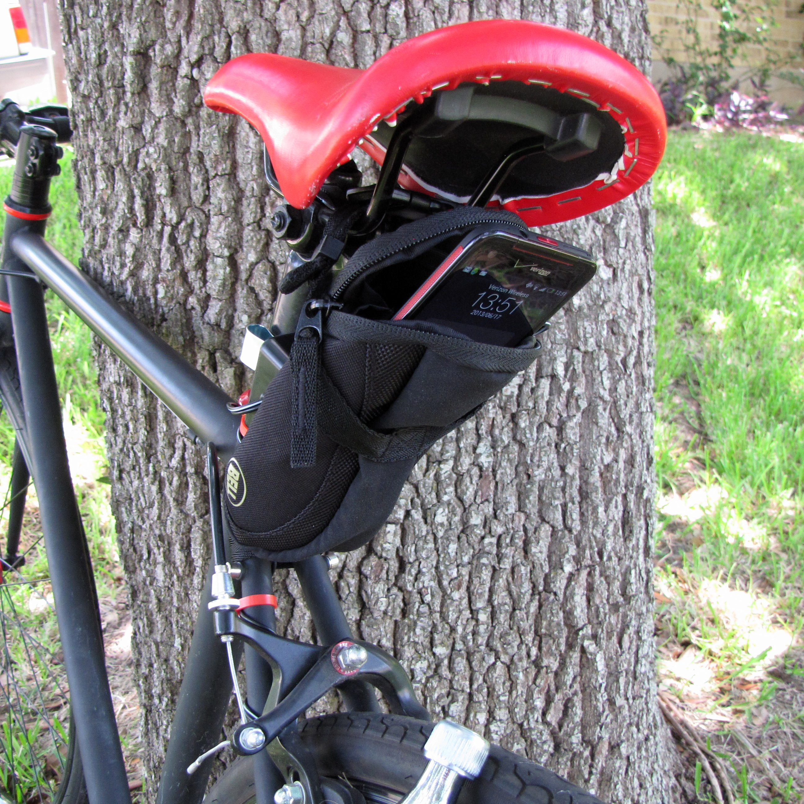
Clip the project box to your bike frame with the broom clip. We chose to mount ours underneath the seat, as shown.

Install the generator.

Mount the generator to your bike according to its directions.

Safely route the AC input cable from the project box along your bike frame to the generator, keeping it well clear of all moving parts. Secure with zip ties.

Cut off the plug at the end of the AC input cable at the generator.

Complete the wiring.

Separate the leads of the cut cable over a distance of about 1-1/2″, and strip about 1 cm of the insulation from each lead.

Secure the bare stripped ends of the leads to the generator output terminals. It doesn’t matter which lead goes to which terminal.

Plug your cell phone into the micro-USB adapter and secure it, with any excess cable, in a zippered saddlebag or other pouch attached to your bike. You’re ready to go!