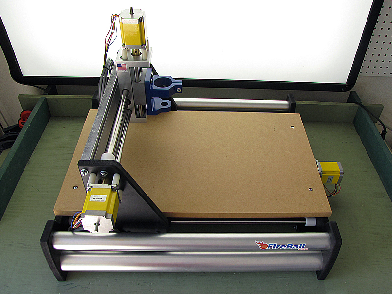
Although the V90 is an entry-level machine, it’s decidedly not a toy. The way it functions is complicated — a platform carries the tool holder; a larger gantry moves the tool back and forth; the frame positions the gantry; and it’s all driven by a motor turning the screw interposed between two shafts. Indeed, this three-axis Cartesian robot is probably the most complex machine I’ve ever built, and I had expected it to be correspondingly difficult to assemble; however, quite the contrary — it’s easier than many common bike repairs. A thriving community actively updates the online build guide, and all the materials were very helpful during my own build.

What will the next generation of Make: look like? We’re inviting you to shape the future by investing in Make:. By becoming an investor, you help decide what’s next. The future of Make: is in your hands. Learn More.

Project Steps

Clean the rails

The bearings in your V90 are made of Oilite, a microporous metal vacuum-impregnated with lubricant. The centerless ground shafts (“rails”) in your kit ship with a waxy, protective coating, that must be removed before they are installed in these bearings, otherwise the waxy material will clog the oilite pores and ruin the bearings. Do not install the shafts in the bearings without cleaning them first!

Moisten a soft cloth with acetone and wipe down the shafts until the surface no longer feels waxy.

Be sure to clean all four rails. There are two smaller, 0.625″ diameter rails for the short horizontal axis, and two larger 0.750″ diameter rails for the long horizontal axis.

Insert the rails into the bearings

Insert each of the longer, 0.750″ diameter shafts into one of the two gantry slides, as shown.

Insert both of the shorter, 0.625″ diameter shafts into the Z-axis assembly.

Assemble the gantry

Mount two of the smaller white, cup-shaped rail end bushings to each of the two gantry uprights, as shown, by inserting the threaded bolts on the bushings into the corresponding holes in the uprights. Secure each with a single nut, just finger-tight, for now.

Slip the rail end bushings over the ends of the two gantry rails.

Install gantry tension rods

Slip the four shorter lengths of threaded rod (“tension rods”) into the four holes in each of the uprights, as shown.

The back (silver) and bottom (black) gantry frame members each have two grooves to receive the tension rods. Slip both frame members in place over the rods, as shown.

Install and tighten gantry bolts

Add a flat washer and a hex nut over each exposed end of each tension rod. Tighten the nuts down finger tight.

Set the gantry upright on the bench, as shown, and tighten each tension rod, with a wrench on each end. Do not overtighten! One turn past finger-tight is plenty.

Adjust the tension on the rods as necessary to square up the gantry. A good test for squareness is that the Z-axis assembly slides smoothly on the rails, without binding.

Install upper lead screw

Choose the side of the gantry on which you want to mount the short-horizontal-axis stepper motor. Both sides have motor mounting holes, and the choice is only one of convenience. Think about clearances and cable pathways in the place you’re eventually going to be using the robot.

Insert the end of the smaller lead screw without the brass coupling through the hole in the gantry upright on which you plan to mount the motor.

Once the tip of the lead screw is between the gantry uprights, slip a bearing assembly, a nylon washer, and a shaft collar onto it, in that order. Note the correct orientation of the bearing assembly, with the narrower end closest to the gantry upright.

Carefully thread the lead screw through the anti-backlash nut in the Z-axis assembly. The anti-backlash nut ships with a small cardboard tube inside it, which will be pushed out as you thread in the lead screw.

NOTE: Do not attempt to remove the cardboard tube in any other way. Likewise, do not remove the lead screw from the anti-backlash nut once it is threaded through. Without either the tube or the lead screw in place inside the anti-backlash nut, it will fall apart, and can be quite tricky to get back together. See this document for more info.

Once the lead screw is through the anti-backlash nut, slip a shaft collar, a nylon washer, and the other bearing assembly onto its exposed end. Push the lead screw in, sliding the Z-axis assembly with it, until the bearing assembly is secure in the far gantry upright.

Adjust the lead screw such that about 3/4″ of the brass coupling is exposed outside the gantry. Position the shaft collars close up against the washers and bearings at each end of the lead screw, and use a 7/64″ Allen wrench to tighten them down.
Install lower drive nut

The lower drive nut is a second anti-backlash nut that comes pre-installed in a bracket with two mounting holes, like the blue one shown here. To install it, you will need two machine screws, six flat washers, and two matching hex nuts.

Pass the two machine screws through the mounting holes in the gantry floor, from the top down.

Slip two flat washers over each exposed screw end. These serve as spacers between the gantry floor and the lower drive nut assembly, and can be removed (or supplemented) later, if necessary, to adjust its height.

Slip the lower drive nut assembly over the exposed screw ends and doubled flat washers.

Add an additional flat washer, and a hex nut, to each exposed screw end. Tighten the hex nuts to secure the lower drive nut assembly. As always, be careful not to overtighten.

Install large rail end bushings

NOTE: My V90 arrived with the table support bars pre-installed on the base ends. If yours did not, don’t fret: it isn’t complicated. Refer to the Probotix assembly guide for details.

Each base end gets two of the larger, white, cup-shaped rail-end bushings. The white “cups” go on the same side of the base ends as the circular grooves.

Secure each rail-end bushing with a flat washer and a hex nut on the ungrooved side of each base end. Tighten the nuts down one turn past finger-tight.

Assemble the base

At least one, and possibly both, of the base ends in your V90 kit will have four small motor mounting holes, arranged in a square, in the center. If you have a base-end without motor mounting holes, start with it. If both your base ends have motor mounting holes, it doesn’t matter which you start with.

Use magazines, phonebooks, rags, or other padding to cushion one base end flat against your work surface, with the grooves and rail-end bushings facing up. Try to get it level, and make sure it doesn’t rock too easily on the bolt heads.

Slip the large 0.750″ diameter guide rails, with attached gantry slides, into the upright rail-end bushings. Note the correct orientation of the gantry slides: With their flats rotated away from the table support bars, the wider part of each flat should be oriented toward the inside of the frame.

Slip the plastic pipe sections–two large and two small–into the corresponding circular grooves on the base end. This is where it helps for things to be level.

Install tension rods

Slip a flat washer onto the end of each of four long threaded tension rods, and follow it up with a cap nut. Tighten each cap nut all the way down with your fingers.

Lift the other base end into place over the upright rails and pipe sections, mating the two free rail ends with the rail-end bushings and the four free pipe ends with the circular grooves.

The tension rods run inside the pipe sections. Lower one into each of the four holes in the upper base end. The flat washers and cap nuts will keep them from falling all the way through.

Secure tension rods

This part is a bit tricky. Fish around with the threaded rod, inside each pipe section, until you hit the hole in the lower base end. Once you find it, lower the threaded rod as far through it as you can.

Once you get each of the four tension rods through the right holes in both ends of the base, grasp the base assembly by the ends, applying pressure along its length to keep everything together, and rotate it into a horizontal position on your work surface.

Put a flat washer over the free end of each threaded rod, and secure it with a hex nut. Again: just finger-tight, at first.

Install gantry

Set the gantry assembly in place on the gantry slides.

Put three machine screws through the three holes at each end of the gantry floor, passing them down through the three mating holes in each gantry slide.

Secure each gantry slide with three flat washers and three hex nuts, one for each screw. Go ahead and tighten them one turn past finger-tight.

Adjust frame

Tighten each of the four long tension rods one turn past finger-tight, using a wrench on each end of each rod.

Adjust the tension on the four rods as necessary until the gantry slides smoothly on the rails from the pressure of one finger.

Assemble long lead screw

Every V90 I’ve seen has the long horizontal-axis stepper motor mounted on the “tool side” of the gantry. If both of your base ends have motor mount holes, however, I haven’t yet thought of any reason why you shouldn’t mount the motor on the “back side” of the gantry. If you’re not feeling adventurous, however, best to stick to the side pictured in the photo.

Pass the long lead screw through the bearing support hole in the base end on the same side that the motor will be mounted.

Once the lead screw is inside the frame, slip a bearing assembly, a nylon washer, and a shaft collar over its end, in that order. Note that the narrower diameter of the bearing assembly should be directed towards the bearing support hole.

Pass the lead screw into the lower drive nut assembly and thread it through the anti-backlash nut.

As before, threading the drive screw through the anti-backlash nut will cause a small cardboard retaining plug to be pushed out. Do not remove this plug in any other manner, and do not back the screw out once you’ve started it in. If the nut does fall apart, don’t worry: It can be fixed. See this document for more info.

Once the lead screw is through the anti-backlash nut, slip the remaining shaft collar, nylon washer, and bearing assembly over its end, in that order. Again, make sure the bearing assembly is facing the right way.

Secure long lead screw

Adjust the lead screw assembly, as before, such that about 3/4″ of the brass coupling is exposed outside the base end.

Seat the bearing assemblies firmly in the base ends and butt the nylon washers and shaft collars close up against them.

Secure each shaft collar in place by tightening its set screw using a 7/64″ Allen wrench.

Install stepper motors

Note: Probotix officially recommends filing or grinding a small flat on the round motor shafts before installation to make it easier to remove them, later. I did not do so, and have not had cause to demount the motors yet, so I can’t say one way or the other. But the machine does work fine, without grinding flats.

Mount both horizontal- and the single vertical-axis stepper motors by first inserting each motor shaft in the exposed brass coupling at the end of its corresponding lead screw.

Rotate each motor to align the four mounting holes in the motor case with those in the V90 frame.

Insert four screws through the mounting holes in each motor case, passing each through a flat washer and a nylon standoff (in that order) before starting the threads in the V90 frame.

Use a Phillips-head screwdriver to turn down the motor mounting screws securely. As always, do not overtighten.

Secure motor couplings

Use a 3/32″ Allen wrench to tighten the set screw in each of the three brass motor couplings against the motor shaft.

Finishing touches

Put the spoilboard in place between the base ends, with the recessed ends of the mounting holes facing up.

Pass a 1/4-20 slotted-head machine screw through each of the spoilboard’s four mounting holes, from top to bottom, and thread it into the corresponding T-nut on the underside of the table support bar. Turn down with a flathead screwdriver, but do not overtighten.

The V90 ships with a tool spindle designed to mount a Model 300 Dremel rotary tool. Mounts for other tools, including popular trim routers suitable for heavier work, are available through Probotix.

If you are using the Dremel tool holder, mount it to the vertical-axis assembly with the four bundled screws using a Phillips-head screwdriver. As always, do not overtighten.

Conclusion

This guide covers construction of the mechanical system--the Cartesian robot--itself. To complete a working CNC machine around the V90 robot, you will need a means to generate G-code instructions, a suitable computer to run the control software, the control software itself, and the interface electronics. See Probotix' document, An Introduction to the FireBall V90 for more information.

If you're building a V90, be sure to check out the official Probotix V90 assembly page and Alan Parekh's build over on Hacked Gadgets.