The Lucien Yeomans “secret” that was almost lost.

Your developing world school needs almost-free machine tools?

Your developing world factory needs unavailable spare parts?

You need a complex part that is too expensive to have made?

Need to bootstrap a factory but only have a few bucks?

No problem!

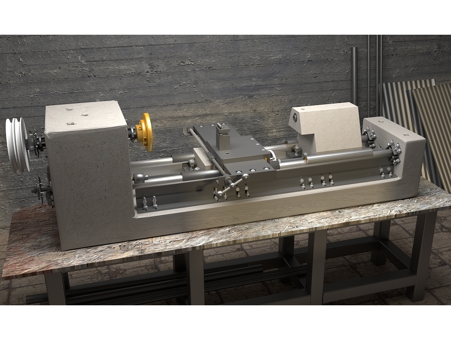
You just need a metal lathe. Metalworking lathes are necessary to the production of almost everything but are very expensive. In 1915, special lathes made from concrete were developed to quickly and cheaply produce millions of cannon shells needed for World War I. Lucien Yeomans, the inventor, won the nation’s highest engineering award for it but sadly the technique was almost forgotten after the war. We re-discovered it as a way to quickly make inexpensive but accurate machine tools for use in developing countries and in trade schools and shops everywhere. We made modern construction practical by replacing the original poured, non shrinking metal with cement grout.

Credits

Design by Pat Delany, rigmatch@yahoo.com

Drawings by Tyler Disney, flowxrg.com

Research by Shannon DeWolfe and David LeVine. Shannon found Yeomans after I had searched for years.

Dimensioned drawings and support at:

http://groups.yahoo.com/group/multimachi…

Many supporting files are at:

http://concretelathe.wikispaces.com/Curr…

The best machine tool reference site in the world is at: http://lathes.co.uk/

Project Steps

Step 1

$150, 12″ Swing, Metal Lathe/Mill/Drill

  • Open source, bottom-up development for emerging economies.
  • Making machine tools accessible to the developing world with a concrete lathe that can be easily and inexpensively built. The machine tools that fueled the Industrial Revolution in the Western World have become too expensive to be used in the places that most need small industries now. This concrete lathe design can change that. Based on a proven early 20th-century design, it can be made in any size and the same techniques can be used to make many different kinds of machine tools.
  • It can be built by a good mechanic using scrap, steel bar and concrete. Builders need only common mechanic’s tools, a drill, inexpensive measuring devices and to get a few small welds done. It is easily converted to drilling and horizontal and end mill operations.
  • Lathe cost is determined by the size of the machine you build and the kinds of good junk you have available.

Step 2

$150, 12″ Swing, Metal Lathe/Mill/Drill

  • Many people will not know what this machine is so…A metal lathe or metalworking lathe is a large class of lathes designed for precisely machining relatively hard materials. They were originally designed to machine metals; however, with the advent of plastics and other materials, and with their inherent versatility, they are used in a wide range of applications and a broad range of materials. This is a 100-year-newer, industrial version of the type shown in the step below. This one, the one below and ours all work in exactly the same way.
  • METAL LATHES ARE THE ESSENTIAL TOOL IN PRODUCING ALMOST EVERYTHING IN OUR LIVES. Simply put, they are used to make almost everything that is round and they also are used to make the rollers that are used to make almost everything that is flat. Lathes can make all the mechanical parts of the milling machines used to manufacture the molds for all the plastic parts used for almost everything.
  • Ours COULD be made in a size that would dwarf this 1500 kg. machine.

Step 3

$150, 12″ Swing, Metal Lathe/Mill/Drill

  • Our idea started with this. What Lucien Yeomans did in 1915 (and we do) is very simple. It is well known that concrete shrinks as it sets up. This is not important when you pour your sidewalk but this shrinkage would force a concrete machine tool out of alignment as the concrete casting “seasoned”. Yeomans solved this problem by casting a concrete frame or “bed” with oversize cavities where the parts would normally go and then let the concrete season and shrink. He would then align the metal parts and hold them in place by pouring a non-shrinking, low-temperature metal alloy over them.
  • Our lathe design is similar to a typical 250kg 225mm swing (chuck capacity) lathe. Our lathe can be mounted with a common 100mm angle grinder that can be used to re-surface vehicle clutches and brakes. Ours was specifically designed to be transportable so it could be taken to Maker Faires and yet would also be highly useful in shops. A better choice for many would have ways 300mm between centers and a 400mm swing. Other parts could be scaled up accordingly and would add little to the total cost. A larger lathe would be even easier to build because there would be more room for components.
  • IMPORTANT! On a larger version, the head stock and foot of the lathe should be enlarged and the lathe bed (base) should be made at least 150mm thick.
  • I would personally recommend that if you have the room, a lathe of 300mm between way centers should be considered. This extra width would provide room for inexpensive tooling that would allow the lathe to do work that few (if any) other lathes could do.

Step 4

$150, 12″ Swing, Metal Lathe/Mill/Drill

  • Quite simple! Construction is really just a series of simple steps that are meant to be doable in primitive conditions.
  • Steel can come from your scrap pile or bought in easily available standard sizes.

Step 5

$150, 12″ Swing, Metal Lathe/Mill/Drill

  • Every part of our lathe can be replaced as parts wear or as improvements are needed.
  • The all-thread type lead screws can be replaced by the Acme or ball screw types.
  • Spindle bushings can be replaced by ball or roller bearings.
  • The carriage can be replaced with special milling or boring types.
  • A compound slide (a swiveling top slide) can (and should) be added.
  • Electronic lead screw or change gear type threading could replace the simple “thread follower” type.
  • Steady and follow-rests can be be added, as can a turret or powered tailstock.
  • The box type cross slide can be replaced by a dovetail type machined on the lathe itself.

Step 6

$150, 12″ Swing, Metal Lathe/Mill/Drill

  • Our goal is not to build the best tool, but one that will work with reasonable accuracy and that can be built by a skilled mechanic using common tools and at the absolute lowest cost.
  • This is my personal humanitarian effort. I designed the lathe as a combination of simple ideas or long-proven technologies. For more information about my projects contact me at rigmatch@yahoo.com.
  • Technologies that I use besides the Yeomans concrete technique.
  • The cartridge, bushing type spindle assembly.
  • Carriage mounting shoes that are connected only by concrete.
  • Supported round ways.
  • Thread-follower threading with wood or plastic clamp jaws that close on a rotating thread that is to be duplicated.
  • On larger lathes, the carriage is held down by weight only. This technique is almost 200 years old.

Step 7

$150, 12″ Swing, Metal Lathe/Mill/Drill

  • Just a few extra sacks of concrete are needed to make a taller headstock, carriage and tailstock. It will let you do jobs few other machines can do. One example is the ability to resurface large truck brakes and clutches.
  • Such a machine may look a little strange but can still be used as a regular screw-cutting lathe.
  • BUT…Even though increasing the size of a lathe so that it can machine large brake drums may take only a few extra sacks of concrete mix, the concrete needed for a general-purpose lathe this size will be measured in tons!
  • This may be confusing, but resurfacing a large iron disk takes far less power and rigidity than having to take deep cuts in a large piece of steel.

Step 8

$150, 12″ Swing, Metal Lathe/Mill/Drill

  • Machine accessories like these often cost much more than than the lathe itself. It does take extra room at the side of the chuck but this is easy to get on our lathe just by making the bed wider.
  • More about this at the end of this guide but you will have to admit that it is pretty cool to be able to have a machine tool that costs 98% less than others and that can machine both a huge brake drum and also make a part as complex as this.

Step 9

$150, 12″ Swing, Metal Lathe/Mill/Drill

  • We use the Yeomans technique but replace the poured metal filler with easily available, non-shrinking cement grout. We use grout or concrete to mount and fit every part of the lathe.
  • Fitting the ways to the bed.
  • Fitting the “shoes” to the ways and the central part of the carriage and then locking them together.
  • Fitting the cross slide to the carriage.
  • Fitting the tail stock to the ways.
  • Fitting the Morse Taper socket in the tail stock.
  • Fitting the spindle cartridge to the headstock.
  • Fitting the thread follower spindle cartridge in the head stock.

Step 10

$150, 12″ Swing, Metal Lathe/Mill/Drill

  • 2 pieces of round, straight steel pipe or bar for the “ways” (the round shiny things that the carriage slides on). ACCURATE WAYS ARE THE MOST IMPORTANT PART OF THE LATHE. Be very careful when you select them. Good pieces of carefully aligned railroad track could be used on larger lathes.
  • Steel bar for the cross slide.
  • Scrap pieces of angle iron and pipe for the spindle cartridge, carriage “shoes” and supports for the ways.
  • Junked pistons to be melted and cast into adapters, bushings or bearing housings. Casting simple shapes is very easy and gives the machine builder the ability to make thousands of different, useful devices and products.
  • Concrete mix, re-bar, fiber additive for concrete, non-shrinking grout.
  • These are the kinds of materials needed to build a 300mm swing (maximum length that would fit on the faceplate) screwcutting lathe that would fit on a workbench. A desktop lathe half this size could also be built. Our optimal “shop size” lathe would have ways 300mm (centers) apart, swing of 450 mm and would weigh at least a thousand kg.
  • The length, diameter and width of the ways are the determining factor in the size of the lathe you build.
  • A lathe the size of a railroad car could be built using the same basic design.

Step 11

$150, 12″ Swing, Metal Lathe/Mill/Drill

  • Steel for the ways will probably require a careful search. Needed are (2) 40mm (or larger) x 2 meter (approx) very straight steel rods or pipes (scrap hydraulic cylinder piston rods?) Check them for straightness by putting the round bars or pipe side by side and shining a bright light between them as you first rotate one, then the other.
  • A known-good lathe could be used to turn or grind the ways round and straight. If you do have ways turned, be sure to check the ways very carefully afterwards because machining a long piece to an accurate diameter can be difficult.
  • Imperfect ways probably could be slowly corrected by the “3 rounds” method that can be found here. The method has not been tested on pipe this large. The 3 rounds method is similar to the centuries-old 3 flats method of truing flat surfaces.
  • Pipe ways should be filled with grout before final adjustments.

Step 12

$150, 12″ Swing, Metal Lathe/Mill/Drill

  • The cross slide can be made using 3 pieces of steel of different widths or built in a more simple version that requires steel of only one width (150mm by 19mm). The 3-piece design is superior because wear is easily adjusted for but it may require cutting a piece of heavy plate to a more narrow width, a difficult job for many.
  • Finding used steel bars may be difficult. Whatever your source of bar, be certain that the ends have been sawed and not sheared. Shearing distorts the bar ends.
  • A more simple way of building the slide will be shown on slide 79 (around there). New approaches, options and time and material saving ideas are constantly sought after and added as found. This project is alive and growing

Step 13

$150, 12″ Swing, Metal Lathe/Mill/Drill

  • Besides the pipe and bar, a few shorter pieces of steel angle iron and pipe will be needed. The sizes of these shorter pieces depend on the size of the machine.
  • Used pistons are a source of castable metal for bushings and adapters. Piston metal is an easily available alloy has been proven durable and non-scuffing in cast iron engine cylinders. Casting metal is a growing hobby in the US and may be much more common in developing countries. In some areas it is even common to have aluminum cookware re-cast.

Step 14

$150, 12″ Swing, Metal Lathe/Mill/Drill

  • Building the wooden form and casting the concrete bed comes first. This is not complicated and a good tutorial for this is a “Make a concrete counter top” type of book available in home improvement stores.
  • Next, select, install and align the ways. A carefully held spacer can be used to set the distance between the ways. A piece of float glass plate can be used to put the ways in the same plane. A ball bearing placed on the plate glass can be used to determine if the ways are level enough for our use.
  • Making the carriage “shoes” (the parts of the carriage that actually slide on the ways) and firmly clamping them over the ways comes next because the wooden form for the concrete carriage is bolted to and then built around them. Firmly clamping the carriage shoes to the ways before pouring the carriage concrete aligns it.
  • Fit the form for the carriage around the shoes and pour the concrete and let it season.
  • If no wood or metal lathe is available, make a temporary lathe out of an auto wheel hub assembly mounted on the headstock and use it to machine spindle bushings or ball or roller bearing adapters.
  • Later, mount the hub and brake assembly on the rear of the headstock and use it as a spindle brake. You will have to machine an adapter to fit the drum to the lathe spindle.

Step 15

$150, 12″ Swing, Metal Lathe/Mill/Drill

  • Make the spindle cartridge assembly from 2 pieces of pipe with simple cast bushings used between them, clamp it in place and align it with a dial indicator mounted on the carriage. Measure from the left, right and center of the carriage. Pour grout through the holes in the top of the headstock to lock the spindle assembly in place.
  • Mount a square or a dial test indicator on the spindle and use it to align the cross slide.
  • The tailstock is made in the same way as the carriage (though in a different shape!). A Morse Taper drill bit held in the spindle can be used to align the Morse Taper socket in the tailstock.
  • Add the smaller parts like the lead screw and handwheel mechanism, pulleys, motor, thread follower and tool post.

Step 16

$150, 12″ Swing, Metal Lathe/Mill/Drill

  • If you or people you know are interested in international development, tell them about this. Please let me know if you do.
  • If you build one, please take lots of pics for us.
  • But mostly I want your comments and suggestions. Send them to rigmatch@yahoo.com

Step 17

$150, 12″ Swing, Metal Lathe/Mill/Drill

  • If you or people you know are interested in international development, tell them about this. Please let me know if you do.
  • If you build one, please take lots of pics for us.
  • But mostly I want your comments and suggestions. Send them to rigmatch@yahoo.com

Step 18

$150, 12″ Swing, Metal Lathe/Mill/Drill

  • Refer to our concrete lathe website for more information about the design.
  • The main Yeomans patent and the two magazine articles about his lathe are near the top of the page. If you don’t study every word you are likely to make serious mistakes.
  • Builders often want to change the designs of things they build. I hope you will really try to understand why I have things in a certain way before you make changes. Write me at rigmatch@yahoo.com to talk questionable points over.

Step 19

$150, 12″ Swing, Metal Lathe/Mill/Drill

  • Rule #1 is to PAY INFINITE ATTENTION TO DETAIL! If you don’t, errors will compound and you will end up with an expensive boat anchor!
  • Build a mock-up first (especially of the carriage). Know the source of every bolt, nut and nail. Don’t make a stupid mistake with something that is this big and heavy.
  • THINK THROUGH EVERY STEP.

Step 20

$150, 12″ Swing, Metal Lathe/Mill/Drill

  • The completed form will look like this.
  • AN IMPORTANT NOTE!! Sharp angles in concrete castings are usually not a good idea. When we are able to update these drawings we will show fillets in place of sharp angles.

Step 21

$150, 12″ Swing, Metal Lathe/Mill/Drill

First one in rural Kenya! Jeremmy Awori is using coffin wood for the form.

$150, 12″ Swing, Metal Lathe/Mill/Drill

  • Jeremmy’s coffin shop is our first Kenyan machine tool factory.
  • I take this guy very seriously! Most people fail at using Google Sketchup, Jeremmy started sending me good drawings in just 1 day! He has his choice of four good internet connections while I have one that works just most of the time.

Step 22

$150, 12″ Swing, Metal Lathe/Mill/Drill

Start with a simple box.

Step 23

$150, 12″ Swing, Metal Lathe/Mill/Drill

Close up the base!

Step 24

$150, 12″ Swing, Metal Lathe/Mill/Drill

Add the sides.

Step 25

$150, 12″ Swing, Metal Lathe/Mill/Drill

Bend the re-bar.

Step 26

$150, 12″ Swing, Metal Lathe/Mill/DrillFit the re-bar into the form.

Step 27

$150, 12″ Swing, Metal Lathe/Mill/Drill

  • The bottom part of the inner pieces should be made at a 45° angle to eliminate the sharp right angles between the headstock and foot to the base. This will be shown in subsequent drawings.
  • Insert the end pieces into the form.

Step 28

$150, 12″ Swing, Metal Lathe/Mill/Drill

Like this.

Step 29

$150, 12″ Swing, Metal Lathe/Mill/Drill

Detail of inserted plastic tubes and bolts. The vertical tubes must be large enough to pour grout through later.

Step 30

$150, 12″ Swing, Metal Lathe/Mill/Drill

Pour the concrete, embed the way stabilizer bolts and then add the concrete needed here. The way stabilizer base shown here should actually extend the full length of the bed except for a gap that will be used as a coolant drain and to remove chips.

Step 31

$150, 12″ Swing, Metal Lathe/Mill/Drill

The completed concrete lathe “bed.”

Step 32

$150, 12″ Swing, Metal Lathe/Mill/Drill

  • Attach the way adjusters. They can be cut from scrap angle iron that could be tapped for adjusting bolts. Locknuts should be added. If necessary, the adjusters could be replaced with hardwood wedges but accurate way adjustments would be much more difficult.
  • After the non-shrinking grout is poured in the way cavities and has time to set up, the adjusters can be removed and used to make other machines.

Step 33

$150, 12″ Swing, Metal Lathe/Mill/Drill

If you want your lathe to be as accurate as possible, these adjustment brackets should be as big and strong as will fit. The lathe can then be run, tested and adjusted before the grout is poured. The brackets can be removed after that but remember to work very gently until the ways are grouted in.

Step 34

$150, 12″ Swing, Metal Lathe/Mill/Drill

  • The Ways: The ways are the most critical component of an accurate lathe. Selection of the steel and accurate alignment are all-important. Yeomans’ lathe used specially ground and hardened round bars that would probably be too expensive for our lathe.
  • Pipe, round bar and hydraulic piston rods come in a great variety. All must be checked for straightness. A good way to do this is to put the 2 pieces side by side, rotate one while pressed against the other and use a feeler gauge or bright light from behind to check for a gap.

Step 35

$150, 12″ Swing, Metal Lathe/Mill/Drill

The way ends are very tightly wrapped in greased sheet metal so that the ways can later be rotated (large pipe wrench with padded jaws?) to unworn areas if necessary. The sheet metal should be tightly kept in place by wire or hose clamps.

Step 36

$150, 12″ Swing, Metal Lathe/Mill/Drill

  • Strong support under the ways makes the use of round ways practical.
  • The angle iron and bar stock should be the heaviest that will fit.

Step 37

$150, 12″ Swing, Metal Lathe/Mill/Drill

Round ways are used here because they can be more easily and accurately made than other possible choices. However, they must be supported from below to avoid sag and vibration.

Step 38

$150, 12″ Swing, Metal Lathe/Mill/Drill

Insert the ways and lightly clamp in place. The supports under the ways are made from angle iron and steel bar. A longer lathe (recommended) should have full length way support. Round lathe ways will both sag and vibrate but a rigid support like this is a simple cure.

Step 39

$150, 12″ Swing, Metal Lathe/Mill/Drill

  • Start with a square-edged way support and once the lathe is running use a flycutter to machine a heavier (1/2”, 12mm or larger) bar to fit the radius of the way. The inner edge of the support bar should be at the center of the way. Even heavier supports could be especially useful near the chuck where the heaviest cuts will most likely be made.
  • If the carriage is is heavy enough (75kg ?), there is less danger of the carriage being lifted by knurling operations or an improperly adjusted cutting tool, and a carriage clamp may not even be needed.
  • A thicker (way radius-shaped 25mm?) way support may be needed to handle high horizontal cutting forces in the area close to the chuck. The location of the vertical way support bolts should be laid out with this in mind.

Step 40

$150, 12″ Swing, Metal Lathe/Mill/Drill

Some makers will not have a factory full of alignment frames.

$150, 12″ Swing, Metal Lathe/Mill/Drill

And they may be working all by themselves.

$150, 12″ Swing, Metal Lathe/Mill/Drill

  • Great care must be taken in aligning the ways but the process is actually quite simple. A machinist-type level will make alignment much easier (this is a Grizzly.com $68 model, a great bargain) but you can do without one if necessary.
  • Use a carpenter’s level to set the ways as level as possible. Use a spacer between the ways to accurately set the separation between the ways. This spacer must be kept level, at the center and at exact right angles to the ways. Make a bracket to hold the spacer in a consistent position.
  • If possible use a dial indicator mounted on this bracket to measure way separation instead of relying on the “feel” of how the spacer fits between the ways.

Step 41

$150, 12″ Swing, Metal Lathe/Mill/Drill

  • Consider the thickness of a thin piece of paper as an accuracy goal. Use a thick, square piece of plate glass (float glass is best) laid across the ways to check (with a feeler gauge) for even contact on all 4 corners. Rotate the glass and check again (the glass plate may not be perfectly flat).
  • Move the glass plate from one end of the ways to the other to make certain everything is correct. Adjust the way supports for even contact under the ways.
  • After the under the way supports are adjusted and tightened, repeat the alignment tests.

Step 42

The carriage and cross slide is really the heart of the machine.

$150, 12″ Swing, Metal Lathe/Mill/Drill

  • The Yeomans lathe carriage was specially designed to make it easy for relatively unskilled workers to make accurate cannon projectiles quickly.
  • Our carriage design is completely different.

Step 43

$150, 12″ Swing, Metal Lathe/Mill/Drill

  • A conventional (South Bend) lathe carriage. Note the inner set of ways that are used for the tailstock.
  • I had to make changes for our lathe in order to use just two round ways and still be able to to get a tool mounted in the tailstock to easily reach a workpiece held in the chuck.
  • I also wanted to make the carriage 1.5 to 2 times as long as it is wide. This “standard” has been common for nearly two hundred years and is done to keep the carriage from “cocking” as it is moved under load.
  • I think slowly and the solution was a long time coming (next step)

Step 44

$150, 12″ Swing, Metal Lathe/Mill/Drill

  • NOTE. The carriage shoes (parts that actually slide on the ways) should be at least as 1.5 times as long as the distance between the centers of the ways. Since there is no room for them at the rear because of the tailstock, they must extend forward along the sides of the headstock. These enlarged holes provide room.
  • The enlarged parts of the holes should be made long enough (150+mm?) for maximum carriage travel.

Step 45

$150, 12″ Swing, Metal Lathe/Mill/Drill

  • The cross slide can be made in several different ways. The method shown requires steel plate in 3 different widths which may be hard to find in the developing world. An alternate way would be to invert the clamping device. Only 2 pieces of the steel the same width would then be needed but care would have to be taken to keep the exposed sliding part
  • An accurately built carriage is critical to lathe accuracy and will take thought and care in construction. I suggest you study this section extremely carefully so that you will be able to adapt components to the sizes of low-cost materials that are available to you.

Step 46

$150, 12″ Swing, Metal Lathe/Mill/Drill

  • Using a pre-cast, seasoned concrete bed is critical to the project and SO is the steel frame for the carriage.
  • Most machine builders would find it almost impossible to build a welded or bolted carriage frame that would have the vital, even contact on all 4 corners. We avoid the problem by making the frame in 2 pieces, clamping them to the ways, and then using concrete to fix the 2 sides in place permanently.
  • When the carriage is cast, the concrete links the two pre-aligned sides together. A simple solution to an extremely hard to solve problem.

Step 47

$150, 12″ Swing, Metal Lathe/Mill/Drill

  • How everything goes together.
  • Every fit is critical; however, if things turn out poorly you can just make a better carriage and swap it out.
  • As long as the ways are accurately made and aligned, everything else is made to be improved upon once the machine runs and has been well tested.
  • Well….for that matter the grout that retains the ways could be chiseled out and the ways adjusted or replaced if it proves necessary.

Step 48

$150, 12″ Swing, Metal Lathe/Mill/Drill

The cross slide lead screw could be either on the leading or trailing edge of the cross slide. If on the leading edge it is closer to the center of cutting forces (good) and more susceptible to chips from machining (bad). If used in the leading-edge position, it should have some kind of an easily removable cover over it.

Step 49

$150, 12″ Swing, Metal Lathe/Mill/Drill

Step 50

$150, 12″ Swing, Metal Lathe/Mill/Drill

The bolts that hold the top slide down must be very strong (use cylinder head studs?) and should be welded to bars embedded deeper in the concrete than is shown.

Step 51

$150, 12″ Swing, Metal Lathe/Mill/Drill

  • The round ways are supported by a bar that is slightly off center so that there will be room for a carriage clamping device.
  • Since a flat surface can only contact a round surface in a very small area, We take advantage of this fact by using just the edges of two flat surfaces to support the ways and to hold the carriage in place. Normally cutting forces are downwards but knurling or a poorly adjusted cutting tool my force the carriage up.

Step 52

$150, 12″ Swing, Metal Lathe/Mill/Drill

On a carriage for a lathe with shorter ways space-saving techniques must be used. These clamp bolts fit into notches cast into the carriage. A longer carriage will be easier to make because the clamps can be external and the inner parts not so crowded together.

Step 53

$150, 12″ Swing, Metal Lathe/Mill/Drill

  • The way support bars and the carriage clamps meet at the center of the ways. The way support bar should actually be shown as a heavy vertical support bolted to a piece of angle iron.
  • The carriage is, in effect, pre-aligned. The two shoes are first leveled and then firmly clamped to the ways. They are not mechanically connected until concrete is poured into the form so that it connects the shoes on each side. Any slight distortion from concrete shrinkage can be adjusted for by putting shims between the shoe and the bushings. The bushings should then be lightly epoxied in place.

Step 54

$150, 12″ Swing, Metal Lathe/Mill/Drill

  • The width of the carriage is determined by the space between the shoes and that is determined by the diameter of the pipe used for the shoes and the distance between the ways. It is very important that length of the shoe should be between 1.5 and 2 times the distance between the way centers.
  • The headstock has oversize cavities so that long shoes can slide inside if this proves necessary to keep the optimal carriage length/width ratio. Just extend the shoes past the clamp mounting tabs and adjust the length of the grouted areas in the headstock so that the longer shoes will slide inside the headstock.

Step 55

$150, 12″ Swing, Metal Lathe/Mill/Drill

These replaceable bushings are lightly held in place by a small spot of epoxy.

Step 56

$150, 12″ Swing, Metal Lathe/Mill/Drill

  • Carriage frame and shoes. Shoes are split pieces of heavy-wall pipe. The inside diameter of the pipe should be about 12mm to 25mm larger than the outside diameter of the way. The bushings will take up this space and could be made from cast iron, bronze or piston metal alloy. The holes in the tabs are used to mount the clamps.
  • The placement of the drilled tabs and pieces of re-bar depend on the size of lathe. Adding a foot to the bed length will allow both a longer carriage and a longer tail stock base. A longer carriage and tailstock will let you spread out the tabs and re-bar. The re-bar should be covered by at least an inch of concrete all around.

Step 57

$150, 12″ Swing, Metal Lathe/Mill/Drill

Tab placement again. The safest way to determine tab placement is to actually model the shoes on the ways. The rear tabs will probably be much closer to the end of the shoes than is shown in the drawing. because they will probably have to extend past the handwheel mechanism. (model it!)

Step 58

$150, 12″ Swing, Metal Lathe/Mill/Drill

  • Where the welded re-bar pieces fit into the concrete.
  • You can see here that the internal clamps (needed on a short bed lathe) cause a little crowding.

Step 59

$150, 12″ Swing, Metal Lathe/Mill/Drill

Build the wooden form for the carriage before the way clamps are attached. Use the clamp mounting tabs to support the carriage (and tailstock) form.

Step 60

$150, 12″ Swing, Metal Lathe/Mill/Drill

  • Cast the concrete over the surface of the shoe in this area.
  • Start the sides of the form at the bottom edge of the “shoe” that slides on the way.
  • The tabs that are welded to the shoes make good attachment points for wooden blocks used to hold the form in place.

Step 61

$150, 12″ Swing, Metal Lathe/Mill/Drill

  • Close in the edge of the form here. Use the widest possible carriage width to support the base of the cross slide.
  • Maximum cross slide support area is necessary because the cross slide mounting bolts are closer together than they really should be.
  • Every design is a series of trade-offs. In this case the trade-off is caused by having to surround the cross slide bolts with enough concrete so that it will not crack if the cross sllde hold down bolts are over-tightened.
  • A fiber additive should be added to the concrete mix and the concrete mixed for maximum strength.

Step 62

$150, 12″ Swing, Metal Lathe/Mill/Drill

  • For clarity, the concrete casting is shown without the embedded re-bar pieces that are welded to the shoes. This particular carriage design can be dropped over the lead screw so that it would be easy to replace it with a different or specialized (milling, for example) carriage. Four threaded rods are used to mount the base of the cross slide. These must be of very good quality steel that is firmly anchored in the concrete. Engine head studs would be a good choice here. They should be cut to the proper length and welded to bars that will anchor them in the concrete below the embedded re-bar.
  • On a small lathe, great care will have to be taken to fit the steel parts that come from 3 directions! This was the only big problem In scaling the Yeomans lathe down 95%!
  • This “cut out” will not be necessary for a long bed lathe that has externally-mounted clamps.
  • The inverted “U” shaped cutout is used only if an easily-removed carriage is desired.
  • Cored holes should be placed so that the milling attachment and the base of the handwheel mechanism can be connected by pieces of all-thread.

Step 63

$150, 12″ Swing, Metal Lathe/Mill/Drill

An overhead view of an externally-mounted way clamp.

Step 64

$150, 12″ Swing, Metal Lathe/Mill/Drill

  • The main lead screw is a piece of threaded rod that does not rotate. The carriage and the tailstock are moved forward by turning nuts that move along the screw. The lead screw is secured by nuts at the foot (end) of the lathe. The carriage and tail stock can be the “drop on” type that is easily removed and replaced. The size of the lead screw could be anything between 18mm and 25mm for this 300mm swing version of the lathe. Bigger is better.
  • Backlash can be compensated for by adding 2 opposed spring (Belleville) washers and an extra nut. The most common lead screw source is the all-thread rods found in metal shops and hardware stores. Commercial all-thread screws with a black finish seem to be of a higher quality. Cross slide lead screws can also come from auto seat adjusters and auto jacks.
  • The quality of the leadscrews is vital to lathe accuracy. Replace the all-thread type with higher-quality screws if possible but the care you take in suppressing backlash is more important.

Step 65

$150, 12″ Swing, Metal Lathe/Mill/Drill

  • This carriage mechanism is quite simple. Unlike most lathes that have complex “aprons” with many parts, this one just has 5 simple parts that can be built using just a drill, hacksaw and file. The handwheel can be replaced by a bicycle sprocket that later can be linked to another sprocket in an easier-to-reach location. Or, to get the lathe up and running in a hurry (so it can make its own parts), just make the mounting plate, add a nut that can be turned by a wrench to move the carriage forward and heavy springs to pull it back.
  • The clamp parts, grooved nut and handwheel adapter could be easily made at this stage. One side of the clamps (above) can be shimmed to reduce backlash in the carriage hand wheel clamp device. The coupling nut could have a larger grooved hub pressed over It to make a larger clamp contact area. If a milling attachment is going to be added, the base can be made longer so that a bolt can go below the leadscrew and connect to it to the milling adapter.

Step 66

$150, 12″ Swing, Metal Lathe/Mill/Drill

A VERY STRANGE THING! The only real criticism of the machine design concerns the location of the handwheel. If this bothers you then replace the hand wheel with a bike sprocket and chain leading up to another sprocket mounted higher up and closer to the operator. Make a simple cover to keep the chain and sprockets free of cuttings.

Step 67

$150, 12″ Swing, Metal Lathe/Mill/Drill

The base plate of a 3-piece cross slide. It is made at least 25mm more narrow than the part above so that there will be clearance for the slide clamps. This is not necessary on a slide that has inverted clamps. The nuts actually fit into counter-bored holes and the excess stud length is ground off flush with the slide that should be thick enough (19mm?) to avoid grinding off much (if any) of the nuts.

Step 68

$150, 12″ Swing, Metal Lathe/Mill/Drill

  • An angle-iron alternative to the split-pipe shoe. The brass wear strips could be eliminated if necessary.
  • SPECIAL NOTE: This is not the best engineering solution since there is great pressure at the way contact area. BUT it is easily made, cheap and very accurate if carefully aligned. The ways can be rotated slightly to adjust for any excessive wear.

Step 69

$150, 12″ Swing, Metal Lathe/Mill/Drill

  • When grinding an optical flat (or other kind of flat), three disks are used. Let’s call them “A”, “B” and “C”. Put A on B with some fine grinding compound. Grind until a frosted finish is seen on both surfaces. Now do the same with B on C. Now repeat with C on A until the surfaces have 100% contact. Repeat this process until it takes little (or no) work to get 100% surface contact in all three combinations. The surfaces will then be very flat. It works on steel as well as on glass.
  • How does it work? A on B results in a spherical surface, B on C results in a less spherical (closer to flat) surface, C on A results in an even closer to flat surface after grinding. Each pass results in flatter spheres. If A is concave, B is convex and C is concave. When A and C are ground to each other, they hit the high points first. Now either A or C is concave and the other is convex. Grinding both against B results in the flats being averaged. Eventually they are flat enough. Gravestones and monuments are often VERY flat. They make good layout tables!
  • The plate edges are also important since the clamps are screwed to them. Edges of hot-rolled steel plate are not flat and this has to be corrected since clamp parts are screwed to them. Carefully file the edges flat while constantly checking with a square. Keep flipping plates over and end-for-end while checking them side by side until you get them filed to identical widths, with parallel sides and flat edges. Thanks to Dave LeVine for this.

Step 70

$150, 12″ Swing, Metal Lathe/Mill/Drill

The cross slide lead screw could be a piece of threaded rod but parts from an old gear puller could work well since they usually have a fine thread and the screw is hardened. Later you could make an extra nut with a similar thread and use it with cupped washers to eliminate most end play.

Step 71

$150, 12″ Swing, Metal Lathe/Mill/Drill

Mounting holes are counter bored 25mm for the nuts that hold it down.

$150, 12″ Swing, Metal Lathe/Mill/Drill

Like this

Step 72

$150, 12″ Swing, Metal Lathe/Mill/Drill

  • Use transfer screws to accurately align the base plate and the 4 studs that are sticking up through the concrete carriage. Screw these transfer screws part way into nuts and screw the nuts onto the ends of the studs. Align the base plate over the transfer screw pointed ends and tap with a hammer. Heavily punch the first hole position, fit and align the plate and mark the remaining holes one by one. Deepen these light marks with a regular center punch and drill with a small pilot drill.
  • Make your own transfer screws by epoxying short, sharpened pieces cut from an old Allen wrench into set screws the same size and thread as the carriage studs.
  • If you use an endmill as a counter bore tool, do it after each hole is bored and before the plate is moved, otherwise the hole center will be hard to locate.

Step 73

$150, 12″ Swing, Metal Lathe/Mill/Drill

  • The top slide should be at least 1.5 times as long as it is wide in order for it not to jam when it is advanced under pressure.
  • The tool post should be at least 400mm square. Another similar sized one could be drilled to fit boring bars or a drill chuck (maybe taken from a broken electric drill?).

Step 74

$150, 12″ Swing, Metal Lathe/Mill/Drill

An easily made slide adjuster. The arrow points to a cut in the steel bar. The outer part of the bar is threaded and as the screw is tightened it bends the thinner part of the bar in toward the cross slide. The brass bar is optional.

Step 75

$150, 12″ Swing, Metal Lathe/Mill/Drill

  • Another way to build machine slides is to invert the clamp. This lets you build the cross slide assembly using just two pieces of steel of the same width. This may be more economical and in some areas might be the only way practical. The disadvantage is that metal particles from machining may get between the clamp and the slide. Leather wipers attached to the edges of the top pieces of the clamp should help with this. Wear could be adjusted for by judicious filing or adding a thin shim.
  • A common way to build something like this is to fit it a little too tight and add very thin shims to make things move smoothly. The shims can be removed as the parts wear in and play develops. Another difficulty with inverted clamps is that an additional “compound” slide is made harder to mount because of the more narrow mounting surface. A temporary, light-duty clamp could be made from carefully fitted angle iron.

Step 76

$150, 12″ Swing, Metal Lathe/Mill/Drill

Cross slide alignment: Use the dial test indicator to measure from the end of the spindle to the top and the edge of the cross slide is it is moved from one end to the other. Be certain that the spindle does not turn as you do this.

$150, 12″ Swing, Metal Lathe/Mill/Drill

An alternative way of aligning the cross slide is to use a square.

Building any kind of a low-cost machine tool takes a lathe of some kind. The aluminum or zinc/aluminum alloy castings could be turned on a good wood lathe but it would be much easier to use your concrete lathe bed and carriage as a “temporary” lathe. Huge savings are possible by casting and turning your own bushings and adapters.

Step 77

$150, 12″ Swing, Metal Lathe/Mill/Drill

  • A great many front-wheel-drive and four-wheel-drive vehicles (but not all), use a complete spindle assembly which includes wheel bearings, wheel mounting studs, and mounting structures.
  • Be aware that some are held together by a center bolt; often the end of a stub axle which is splined. The splines do not matter. The mount can go into the concrete (if the bolts are put in place first), and the faceplate can mount where the brake and wheel did. The old stub axle can complete the drive system.
  • While this will not make a hollow spindle (one with a through hole for long workpieces), it is a fine spindle for making the relatively short pieces for a good spindle capsule and for pulleys.
  • Using cast aluminum pulley blanks, you can make drive and reduction pulleys for “serpentine” belts (multi-groove type K belts are common in automobiles) which have lower losses and less slippage than more common “V” belts. The pulleys are simple if you can grind a 40-degree tool and the belts can be run “inside out” for initial machining of the final drive parts.
  • While building a lathe to make a lathe is not the only way to make a good lathe, it is often beneficial and the less-desirable lathe can still be used to do maintenance when the better lathe is finished. While it lacks a lot of utility (like the ability to turn long workpieces), it is much better than no lathe.
  • If the spindle used a disk brake, reversing the disk makes a good faceplate and, if the “hat” is deep enough, a cup chuck.

Step 78

$150, 12″ Swing, Metal Lathe/Mill/Drill

  • This is typical of a drum brake setup used on many vehicles. The drum will come off the spindle without too much trouble in many cases. Reverse the drum, add screws (for jaws) and a simple 3- or 4-jaw “cup chuck” can be made. As with the prior spindle design, while it is far from perfect it will work to make parts and train operators.
  • Machining pressure plates, brake rotors, etc. does not need a hollow spindle.

Step 79

The main spindle and cartridge assembly.

Many kinds of lathe spindles can be used but for our purposes they should all be enclosed in an outer pipe “cartridge” that could be embedded in concrete after it is aligned.

$150, 12″ Swing, Metal Lathe/Mill/Drill

The outer part of the spindle cartridge can be made from a piece of pipe (like the outer part of a hydraulic cylinder), bushings you cast yourself out of piston metal, a thrust device to keep the spindle from moving back and forth and a hollow or solid spindle (like the piston rod of a hydraulic cylinder). The whole assembly is first aligned in the headstock and then (naturally) locked in place by pouring in non-shrinking grout.

Step 80

$150, 12″ Swing, Metal Lathe/Mill/Drill

The outer tube protects the spindle and bushings from the concrete. If the outer tube is large enough, the bushings can later be replaced with ball or roller bearing adapters so that a higher speed spindle can replace the initial slower speed bushing type spindle. Adjusters are shown here but the front adjuster could be replaced with a steel washer between the bushing and the chuck backplate, and the rear adjuster replaced with a simple steel collar that could be moved in order to eliminate end play.

Step 81

$150, 12″ Swing, Metal Lathe/Mill/Drill

Spindle lubrication: On the main and on the thread follower spindle bushings, cut an “O” ring groove here. Drill and tap the outer body of the cartridges for a 90-degree fitting for an oil line and grout the oil line in place with the spindle.

Step 82

$150, 12″ Swing, Metal Lathe/Mill/Drill

Bushings can be cast in almost every size!

Step 83

$150, 12″ Swing, Metal Lathe/Mill/Drill

The “universal” shape for for every casting used on the lathe. It can be used for spindle bushings, ball or roller bearing housings, adjusters and a chuck back plate. It is very simple and is easily cast in the most primitive conditions.

Step 84

$150, 12″ Swing, Metal Lathe/Mill/Drill

The chuck back plate (mount) is seemingly simple, but if you have to buy one it could cost more than the lathe itself! If you make your own, the two most common choices may be either a piece of cast iron that could be turned down to size or to make one from an aluminum casting. A cast aluminum back plate should have two clamp bolts and nuts (not tapped) on each side and an added steel safety collar. The hub will have to have a large enough diameter so that there will be clearance for the nuts.

Step 85

$150, 12″ Swing, Metal Lathe/Mill/Drill

  • The front adjuster is not really needed and future drawings will not show it since the chuck should be as close to the headstock as possible.
  • **BUT**This type of adjustment device is extremely useful for many things. It can be used to adjust end play and also be used to retain pulleys and milling cutters without having to cut a thread on the spindle (difficult). It can also be used to gently force off parts that are stuck on a shaft.
  • Keep this wonderful device in your mental tool box!

Step 86

$150, 12″ Swing, Metal Lathe/Mill/Drill

  • Use an old flywheel as a combination faceplate and chuck.
  • A slow-speed lathe drive could be a shaft with a starter pinion gear and the flywheel ring gear.

Step 87

$150, 12″ Swing, Metal Lathe/Mill/Drill

A simple clamp like this can be used on the flywheel/faceplate.

$150, 12″ Swing, Metal Lathe/Mill/Drill

Or this.

Step 88

$150, 12″ Swing, Metal Lathe/Mill/Drill

A ring or “bell” chuck could be made like this simple 150-year-old design. The problem with this kind of chuck is that it is more difficult to adjust. Adjustment is easier if there is a center in the end of base of the chuck and a workpiece is held between it and the tailstock center before the chuck bolts are tightened.

Step 89

$150, 12″ Swing, Metal Lathe/Mill/Drill

A modern light duty design for delicate work. Bell and ring chucks may be more difficult to use but it is hard to beat the price of one you make yourself.

Step 90

$150, 12″ Swing, Metal Lathe/Mill/Drill

  • A scrapped hydraulic cylinder could provide both the spindle and the outer part pf the spindle cartridge.
  • The piston rod should be at least 37mm (50 to 100mm is much better) in diameter. It should be at least 200mm longer than the headstock is long.

Step 91

Alternative Spindle Designs

  • An original Multimachine spindle design that is heavy-duty and very accurate. You may recognize it as the common bicycle front axle type. Spindle size could be based around the sizes of inexpensive automotive tapered roller bearings.
  • This type of spindle will require more machine work but, if this spacer was bored on the ends to accept the outer part of the roller bearings and then used as the outer part of the bushing-type spindle cartridge, the simple bushing-type spindle could be made to “bootstrap” this more complex, high-speed spindle at very low cost.
  • A bushing-type spindle should be replaced by a ball or roller type if the lathe is to get much use as a milling machine since milling speeds are higher than normal (home-made) lathe spindle speeds.

Step 92

$150, 12″ Swing, Metal Lathe/Mill/Drill

If the ends of the outer spindle tube were bored to the size of an available automotive (cheap) tapered roller bearing, a simple bushing could be used at first and a higher speed roller bearing spindle used later. Whoever bores these ends should have a sample bearing to use to check for a proper fit

Step 93

$150, 12″ Swing, Metal Lathe/Mill/Drill

An accurate home-built chuck. Plans here.

Step 94

$150, 12″ Swing, Metal Lathe/Mill/Drill

Temporarily, the adjuster could be replaced by the sprocket hub if a steel washer was used between them.

Step 95

$150, 12″ Swing, Metal Lathe/Mill/Drill

Spindle alignment. Slide the spindle so at least 8” sticks out the front of the headstock, then use a dial test indicator to measure to the spindle to both sides and the center of the carriage as the carriage is moved forward and backward. After the spindle has been accurately aligned, pour in the grout to lock it in place. This makes the spindle parallel to the ways, which is all-important.

A great spindle alignment video : http://www.youtube.com/watch?v=ZaIuHNFIF…

Step 96

$150, 12″ Swing, Metal Lathe/Mill/Drill

  • The headstock, spindle and flywheel/faceplate assembly can be as simple as an inverted engine block, crank and flywheel that has had the main bearing inserts carefully drilled and the main bearing caps drilled and tapped for grease fittings. A lathe with a 600mm to 900mm (or larger) swing could be easily made this way. Just remember that the largest Yeomans shell-making lathe weighed 9000 Kg, so scale accordingly!
  • An engine block headstock should probably kept at under 200 rpm since the bearing inserts were meant to be used with a pressurized oil system. Grease every few hours at first until you make sure that nothing overheats.
  • A very accurate headstock can be made this way since the main bearing inserts can be shimmed so that there is very little clearance between the bearing insert and the crankshaft/spindle. This tight fit is another reason to use low crankshaft speeds only.
  • Take great care when you drill the bearing insert grease hole since the insert is easily bent or scratched. carefully remove any burrs caused by drilling. Clean everything carefully; a tiny piece of debris will cause big problems.
  • Needless to say, the shims will have to have matching grease holes!
  • To get these low spindle speeds, a very large (wooden?) pulley will have to be attached to the nose of the crankshaft

Step 97

Thread follower threading

  • The thread follower chuck rotates at the spindle speed and is driven by bicycle sprockets and chain. An idler should be added so that the chain can be adjusted or removed when not needed. There is a limit to bicycle chain speeds so use a motorcycle chain for speeds much over 70 RPM (which is 3 times the speed you should start threading with anyway).
  • To cut a thread, a sample piece of threaded rod is held by the follower chuck and is manually clamped in the wooden or plastic block clamp that is attached to the carriage. This pulls the carriage at the proper speed for cutting a duplicate of the sample thread.
  • The follower spindle cartridge is first aligned and then grouted into the headstock.
  • Drill and tap the outer tube for an oil line fitting and grout the oil line in place.

Step 98

$150, 12″ Swing, Metal Lathe/Mill/Drill

  • The thread that is cut could be unusually accurate because the wooden (or plastic) block should average out imperfections in the sampled thread. Special note: Threading on a lathe always requires practice even if you use the best equipment. Threading usually takes multiple passes with the threading tool.
  • You won’t find a device like this described anywhere else but I have built and used one on the original Multimachine. The follower spindle should have an oil line run to it as was described for the main spindle. Half-inch water pipe is about 5/8” ID so this, 2 bushings and a piece of 12mm rod either threaded or epoxied into a discarded drill chuck
  • For a large lathe, the length of the clamp should be increased and larger diameter sample screws made.
  • Our device will require extra practice to learn how to “pick up” the existing thread on subsequent passes but this should not be too difficult because the wooden clamp can be “eased on” instead of suddenly engaged.
  • Compressed air “help” could also be added to a large lathe. An air cylinder could be used to close the clamp on the thread and carefully regulated air pressure supplied to an air cylinder used to add a little push to the other side of the carriage.
  • The picture shows the need for careful modeling before concrete is poured. The clamping device location can be adjusted by simple changes in the shape of the wooden block but come as close as you can to good initial alignment.

Step 99

$150, 12″ Swing, Metal Lathe/Mill/Drill

The original thread follower as installed on the Multimachine.

$150, 12″ Swing, Metal Lathe/Mill/Drill

Our thread follower design may seem strange to some but it allows us to cut threads without needing a stack of change gears like this!

Step 100

$150, 12″ Swing, Metal Lathe/Mill/Drill

The tailstock has a frame that is exactly like the carriage. Except for the difference in shape, construction is similar.

Step 101

$150, 12″ Swing, Metal Lathe/Mill/DrillA long nut or handwheel should be added here.

Step 102

$150, 12″ Swing, Metal Lathe/Mill/Drill

  • An all-thread coupling nut can be cut in this way and then be pressed slightly closed in order to reduce backlash to a minimum. This is important because play in screw threads causes many accuracy problems.
  • An alternative to this is using an extra nut and spring (bellville) washers as shown on the carriage handwheel drawing.

Step 103

$150, 12″ Swing, Metal Lathe/Mill/Drill

  • If you use a Morse Taper socket, a slot should be cast into the tailstock concrete so that a wedge can be used to knock loose a Morse Taper tool.
  • Naturally, the slots should line up!
  • Something should be welded to the back of the MT socket or grooves cut into it so it will not turn or pull loose from the grout.

Step 104

$150, 12″ Swing, Metal Lathe/Mill/Drill

Align the socket before grouting by using a Morse Taper drill accurately held in the headstock chuck.

Step 105

  • Keep the lathe at low speeds for safety (highly recommended ) if there is any chance poorly trained workers will be around it. Long sleeves or long hair and a fast turning chuck can be a fatal combination
  • Low speeds mean that you can use anything from treadle power (next step) on up.

$150, 12″ Swing, Metal Lathe/Mill/Drill

  • You will have to click to enlarge the picture but it is well worth careful study because it shows the power that can come by gearing a lathe to turn very slowly.
  • We can easily achieve slow speeds on our lathe by using a flywheel as a chuck backplate and driving it with a starter motor pinion gear mounted on a shaft and pillow blocks.

Step 106

Make a milling machine

A device like this will be especially useful if the ways are as wide as possible since the vertical slide fits between them.

Step 107

$150, 12″ Swing, Metal Lathe/Mill/Drill

  • 2 long bolts should be used to connect the base of the milling adapter with the handwheel base plate.
  • The bottom of the adapter should be greased and then grouted to the carriage so that it can be refitted in the same place after it is removed.

$150, 12″ Swing, Metal Lathe/Mill/Drill

Rear view that shows attachment points.

Step 108

$150, 12″ Swing, Metal Lathe/Mill/Drill

  • A J.V. Romig milling cross slide design. We mount it vertically instead of horizontally .
  • Original plans for this design are in bench-mill.pdf found here.

Step 109

$150, 12″ Swing, Metal Lathe/Mill/Drill

  • The sizes of the steel bar and the distance between the shoes will determine actual dimensions of the cross slide parts.
  • The cross slide handle position probably should be reversed.

Step 110

$150, 12″ Swing, Metal Lathe/Mill/Drill

The slide base is necessarily a bit narrow since it has to fit between the shoes. The slide clamps should be the adjustable type (shown some steps above) so that the assembly can be kept tight.

What if you could cut training time from years to just a few weeks

The slide base is necessarily a bit narrow since it has to fit between the shoes. The slide clamps should be the adjustable type (shown some steps above) so that the assembly can be kept tight.

In a rush to build one?

  • Delete the tailstock for now but make a bigger tool post that can hold a large drill chuck. Use quick-setting concrete. Use no castings for bushings; buy standard sizes instead. Use just store-bought bushings and steel.
  • Make the spindle and ways from accurate DOM tubing. Use angle iron for carriage shoes. Don’t use brass wear strips so the shoes can be lapped (using valve-grinding compound) to the ways.
  • Use a flywheel and hub that is cut from the end of a crankshaft and then pressed and brazed into the end of the hollow spindle. A hole can then be bored through the crankshaft stub.
  • Materials will cost a little more but all could be easily bought or ordered online.

This is just my idea

  • It is extremely difficult for many workers to make an accurate, complex workpiece if it has to be constantly moved between different kinds of machine tools.
  • The cost of these tools, chucks, vises and adapters can be MANY times the cost of the basic lathe.
  • Why not make it possible to do most or all the work on the basic lathe without having to move the workpiece?

Background

$150, 12″ Swing, Metal Lathe/Mill/Drill

  • Our starting point is this $10,000 lathe accessory that was once used by the U.S. Army. It could be used to mill, slot, drill and grind parts mounted on the lathe chuck. A tool like this would let us make a part that would be similar to our demo piece. It would be done by reversing the part in the chuck just one time. Our problem was to make a similar device that would also be able to tilt up and down while costing 99% less.
  • Learn about the Versa-Mil here.

Auxiliary Spindle

$150, 12″ Swing, Metal Lathe/Mill/Drill

I can’t draw well enough to draw a complete powered auxiliary spindle (help wanted!) so I will show it in parts. The front end of the simple body casting is shown. The body could be cast from simple piston metal or a Zamac zinc/aluminum alloy. Extra castings should be made so that spindles for special work could be easily constructed.

$150, 12″ Swing, Metal Lathe/Mill/Drill

The back end. A bronze bushing should be inserted in the end and a collar added to the shaft to keep everything together.

Bit holders

$150, 12″ Swing, Metal Lathe/Mill/Drill

The easiest bit holder is our old friend, the Morse Taper socket. The rear should be annealed so that it can be drilled for the shaft used to drive it. The housing should have a matching slot so that a wedge can be used to knock the cutting tool or drill chuck loose.

Mount for spindle

$150, 12″ Swing, Metal Lathe/Mill/Drill

  • The mount for the spindle that allows it to be moved in and out, rotated and tilted up and down.
  • Sorry about the drawing quality.

$150, 12″ Swing, Metal Lathe/Mill/Drill

  • Another view.
  • Note that the vertical rails could be extended and a crossbar, lead screw and handwheel added to the top. If two guide rails were added to the inner side of the round disk, the bit could be fixed at a 90-degree angle while it is raised and lowered.

$150, 12″ Swing, Metal Lathe/Mill/Drill

  • Top view.
  • These are not Tyler Disney drawings obviously! They are just the best I can do at the moment.

Optional: Vertical Adjuster

$150, 12″ Swing, Metal Lathe/Mill/Drill

  • Idea for an added vertical adjuster. The collar should have set screws (with brass tips) so that the angle of the cutting device can be maintained while it is raised and lowered.
  • This device could be a Make project all by itself.

$150, 12″ Swing, Metal Lathe/Mill/Drill

Use circular protractors to set the angles (including the locked main spindle).

$150, 12″ Swing, Metal Lathe/Mill/Drill

A rotary table would normally be used to very slowly rotate the spindle while an arc was being cut on our complex project. A very expensive way of doing things!

$150, 12″ Swing, Metal Lathe/Mill/Drill

  • A much cheaper alternative. Let the weight of the handle slowly rotate the spindle and workpiece while milling. Adjust the weight to mill at the proper feed rate.
  • The workpiece needs to be clearly marked first.

Powering the aux. spindle

  • The most difficult problem since the needed, small 1/2 hp. variable-speed motor could be expensive. A carefully supported electric drill motor could be used but cheap air drills would be lighter and take less room.
  • High air consumption will be a problem unless a BIG air storage tank is used. Consider using an old propane storage tank if you can’t find anything better. Be very careful if you do this and don’t weld on the tank!
  • For a proper job, buy an eBay variable-frequency three-phase converter and junked three-phase motors. Switch the converter between the main drive and the auxiliary spindle.

But wait, there's more!

  • Dimensioned plans;
  • Chucks and clamping devices;
  • Cutting tools and fluids;
  • And more are here.

$150, 12″ Swing, Metal Lathe/Mill/Drill
STILL MORE! 3 more of my open source tools.

$150, 12″ Swing, Metal Lathe/Mill/DrillSTILL MORE! 3 more of my open source tools.

The glory of the Multimachine

$150, 12″ Swing, Metal Lathe/Mill/Drill

  • The Multimachine is a great choice for a machine that can do virtually all machining operations. Easily transportable since it is easy to disassemble and then reassemble without losing alignment.
  • The “store bought” cross feed table should be replaced with one made from bolted steel plate (like the one on the concrete lathe) that will cost much less and actually be more rigid.
  • The overarm swings down to support the end of a horizontal milling arbor. Horizontal milling may seem obsolete but cutters are cheap on eBay or can be made more easily than end mills.
  • Disadvantages of the machine are: the short lathe bed (even though almost lathe work is done on workpieces less than 150mm long) and the cost and availability in the developing world of the 200 to 300mm wide steel plate that is used to make one block slide easily and accurately against the other.
  • http://opensourcemachine.org/ http://groups.yahoo.com/group/multimachi…

Other Devices

$150, 12″ Swing, Metal Lathe/Mill/Drill

  • A very old commercial model.
  • Sorry, don’t know the source of the picture so I can’t give credit for some hard work.
  • More here.
$150, 12″ Swing, Metal Lathe/Mill/DrillMy Genny, a multiperson treadle-powered alternator that can be used for village lighting, cell phone charging or mechanical power to drive many kinds of machines (like ours!).

$150, 12″ Swing, Metal Lathe/Mill/Drill

  • The big Genny secret! The piston and connecting rod come out the bottom of the engine block so that it can be the major part of an almost unbreakable multi-person treadle drive. A vehicle alternator requires much more power than one person can provide.
  • http://dir.groups.yahoo.com/group/africa…
  • Using 2 pistons and rods may be stronger but they are hard to set up and keep in exactly the same plane. If they are not perfectly parallel most pedaling effort is wasted.
  • The belt will try to slip on the small pulley. Use an auto belt idler to get the best “wrap” around it.
  • The connecting rod can be extended by cutting it and welding a pipe spacer between the 2 pieces.
  • Threading the top of the piston for hold-down bolts is not durable. I would use “J” bolts or 4 external bolts through drilled steel bars on the top and bottom for additional support. Using both methods together should be considered for a low maintenance generator.
  • The treadle board and frame could be made from pallet wood.
  • Drill the main and rod bearing caps for grease fittings and keep well greased.

Conclusion

Access to a machine shop for a few simple jobs, a $68 machinist level and quick-setting concrete would make construction much faster.