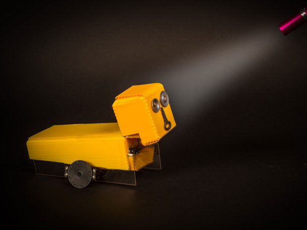
Little robot carts are widely available in kit form, but building your own can be much more rewarding. You’ll see for yourself how the components work, enabling you to customize your cart and even create a new version that’s entirely your own.
This project is an ideal way to get started with simple robotics. It’s so basic, it doesn’t even need a microcontroller. Three timer chips provide enough intelligence to steer the cart in response to a flashlight and back up if it hits an obstacle.
SERVO HISTORY
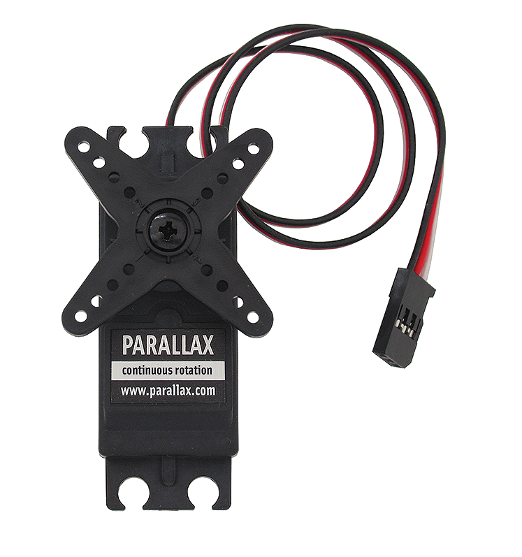
Servomotors are the heart of this cart. Marketed originally for tasks such as moving the flaps on a model aircraft or the rudder on a model boat, they turn to a prescribed angle and then hold that position while waiting for further instructions.
You can control servos using off-the-shelf devices marketed by servo manufacturers, but many makers use microcontrollers for the job. The trouble with just downloading a block of Arduino code is that you won’t understand what’s really going on. The best way to learn is by benchtesting your own motor and driving it with your own hardware.
Project Steps
SERVO SETUP
For this project, I used SpringRC’s SM-S4303R servo. It’s relatively cheap and comes with a wide variety of parts to fit its shaft, including a wheel that will be ideal for our purposes.
You can use a different servo if you prefer, because they all understand the same codes. However, for this project it must be a continuous rotation servo, meaning that the shaft rotates continuously instead of just moving to a selected position and stopping there. (Catalogues don’t always make this distinction clear, so shop with care.) Also, be sure to get a so-called “analog” servo, which is less expensive and less fussy about timing than the “digital” type.
All servos have three wires. The red and black wires supply power to the motor. A third wire of a different color carries the codes that tell the motor what to do.
Servos traditionally use 4.5VDC. The SMS4303R is rated for up to 6VDC, but because you’ll be running it for extended periods, and because some people may want to substitute a motor of their own, I’m going to stick with 4.5V.
SERVO CONTROL
Codes for controlling a servomotor can be generated by a plain old 555 timer. I’ll use 6VDC to power the 555, because I want its output to activate a 5V relay. Obtaining the dual power supply of 4.5V and 6V, with a common ground, is easily done by tapping into a battery pack, as shown in Figure A.
You may need a 30W soldering iron to provide sufficient heat for attaching the wire shown in Figure B.
The test circuit is shown in breadboard format in Figure C, and as a schematic in Figure D.
When you turn the 100K trimmer potentiometer, the motor rotates forward or backward at different speeds. Great! But how does it work?
The timer generates a series of pulses, each lasting about 1 millisecond (ms) or longer, determined by the trimmer. A pause of about 18ms between each pair of pulses is established by the 330K resistor. For all continuous servos, a pulse length of 1ms means “turn clockwise,” a pulse of 2ms means “turn counterclockwise,” and 1.5ms means “stop.” Intermediate pulse lengths make the motor turn more slowly. This is illustrated in Figure E.
The high pulse, and the pause until the next one, should add up to a total cycle time that is always 20ms. But the 555 circuit doesn’t work this way. When you lengthen the high pulse, the pause between pulses remains the same, so you actually increase the total cycle time. How can we correct this bad behavior?
Fortunately, we don’t have to. It is a little known fact that servos don’t require accurate input. The motor won’t care if a cycle is too short or too long, or if a pulse lasts for less than 1ms or more than 2ms. Therefore, a cheap 555 timer can control a servo just as successfully as a more expensive microcontroller.
FINDING PHOTOCELLS
Cadmium sulfide photoresistors, also known as photocells, are not as common as they used to be. You want one that has a minimum resistance of 1K or less under bright light. The Silonex NSL4140 from Jameco Electronics should do the job, but if you try a photoresistor that has a higher minimum resistance (4K is typical), you can omit the 4.7K series resistors from the schematic.
The 25K trimmers allow you to fine-tune the photoresistor response. Note that photoresistors do not have a polarity.
Why not use phototransistors, which are more commonly available? Because they don’t have such a smooth, gradual response to changes in lighting. You can try one in the basic circuit shown in Figure F, but I think it will tend to create an “all or nothing” response from your cart.
CART CONTROL
Suppose we have a cart with two wheels, each of which is powered by its own motor. This is a very common arrangement in bargain-basement robotics. When one wheel turns faster than the other, it steers the cart. When the wheels turn in opposite directions, the cart will pirouette.
If you remove the 100K trimmer in the test circuit and substitute a 25K trimmer in series with a photoresistor, you can steer the cart remotely with a flashlight. And if it bumps into something, a snap-action switch can be our cheap-and-simple collision sensor, triggering a third timer in one-shot mode. This closes a relay for a few seconds, bypassing the photoresistors and forcing the cart to reverse away from the obstacle.
The complete schematic is shown in Figure G, and the breadboarded layout is in Figure H.
WARNING
Be sure to include the 1N4001 protection diode across the relay, to suppress voltage spikes. Also, note that your relay may have different pinouts from mine. Check the relay datasheet to identify the pairs of contacts that close when power is applied.
FABRICATION
Because this is a bare-bones cart, I didn’t bother to make it look nice. The initial fabrication from a piece of ABS plastic is shown in Figure I, and the final cart is in Figures J and K. Note that the motors must both face the same way, because they’ll be turning in the same direction.
Double-sided adhesive holds the battery pack under the frame. A DPDT switch controls the power, switching the 4.5V and 6V circuits separately.
Try to balance the cart with most of the weight over the wheels, so that the tail end slides easily across the floor.
TESTING
Use the cart in a dimly lit room. If it runs backward, you have too much ambient light. If it doesn’t run straight, adjust the trimmer potentiometers. Now shine a flashlight at it, and it should stop and back up. If you angle the photocells in different directions, you can illuminate one of them but not the other, to make the cart turn. This works best on a smooth, hard floor that will allow the tail to slide to and fro.
UPGRADES
To increase the speed of the cart, make your own, larger wheels. To make it turn automatically when it backs up, add a tail wheel that pivots through a limited range, as I suggested for a simpler cart project in my book Make: Electronics.
To create some mystery, you could use infrared phototransistors with matching infrared LEDs in a handheld remote. Puzzle your friends by issuing verbal commands to the cart, while you control it secretly with your transmitter.