Make: has featured and reported on some amazing, iconic maker projects over the years. In the magazine’s early days, projects like aerial kite photography (featured on the cover of Make: Volume 01), Mark Frauenfelder’s vibrobots and cigar box guitar, my own Mousey the Junkbot, Evil Mad Scientist Labs’ Bristlebots, Ladyada’s Minty Boost, and many others, ended up becoming emissary projects for the new maker movement. One of my favorites in all of these early, iconic creations was Jerome Demer’s Beetlebot.
The Beetlebot is an especially brilliant little design. Where most robots quickly become intimidating complex and require sophisticated programming to do even the simplest things, the Beetlebot fits the basic definition of a robot (it can sense something and plan and act on that sense) yet it requires only a literal handful of parts and has no brains whatsoever.
This is a really great activity to do with a group of kids where the situation calls for a meaty project, but something not too complex, deeply technical, or time consuming. And the results are something in which young builders can feel a real sense of pride and accomplishment. And they’ll have a robo-critter that is a genuine (although about as basic as you can get) robot. The parts you need to build your own Beetlebot are as follows.
- 2 x 1.5V motors
- 2 x SPDT (single pole double throw) switches with a metal lever
- 2 x AA or AAA battery
- 2 x Terminal connector
- 1 x AA or AAA battery holder
- 1 x Plastic or wooden pearl (spherical bead)
- 1 x 1 inch x 3 inch piece of metal or aluminum
- 1 x Toggle switch for the on/off switches
- Paper clips big and small
- 2 feet of wire, around 22/24 Gauge
- Heat shrink tubing that will fit over the motor shaft and some that will fit over the terminal connectors
- Electric tape and masking tape
The Beetlebot was featured in Make: Volume 12 in 2008. Jerome later made it into a Make: Projects post. There is also an Instructables version of the project with a current discussion in the comments, one that Jerome participates in.
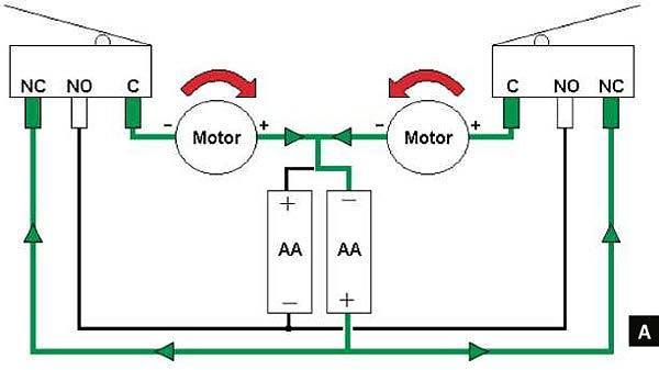
The Beetlebot incorporates a very simply design where the push-button switches on the front of the bot are cross-wired with the robot’s motors. When one of the feelers gets depressed (when it touches an obstacle) and it presses the push-button, it switches the opposite motor on the robot to reverse, backing and turning it away from the obstacle. When the button is released, it moves forward again. This moving forward until an obstacle is encountered, turning and backing up a few seconds, and then moving forward again is just enough of an obstacle avoidance “program” to allow the Beetlebot to navigate a space. This diagram shows how the terminals of the two switches are wired and how they connect to the motors and battery.
Here’s some brief footage of the Beetlebot in action.

Also, in 2009, Kip Kay devoted one of his Weekend Projects videos to the Beetlebot. He runs through the entire build, so you can get an idea of just how easy it is. The hardest parts are orienting and wiring the motors and switches correctly and bending the whiskers. There is very minimal soldering involved.

Our friends over at Solarbotics sell a kit inspired by the Beetlebot kit. Jerome Demers was an intern at Solarbotics and helped them develop the kit.
ADVERTISEMENT


