

Peter Easton and Gary Tietz are both semi-retired engineers, but still enjoy tinkering with software and hardware projects in their spare time.
Together they set out to solve a big challenge for those designing small form factor electronics boards: soldering surface mount components.
Soldering Techniques
There are two basic approaches to soldering components on a printed circuit board (PCB): through-hole and surface mount.
In the through-hole soldering each component has long wires known as leads that protrude from it. These leads fit through holes in the PCB and are soldered individually to pads on the underside of the PCB.

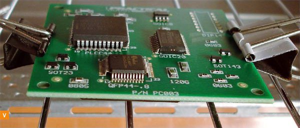
In surface mount, components do not have long leads, rather they have smaller leads that sit atop the PCB. While some surface mount components can be soldered by hand, the widespread approach is to spread solder paste on the PCB pads, place the component and bake in a reflow oven.


Make: What motivated you to make ControLeo2?
Peter Easton: After playing around with through-hole components for a while I soon realized surface-mount was the way to go. I did a lot of research before building my first oven and used a Rocketscream shield to control it. I was very frustrated with it, and designed a multi-relay controller with a larger screen to fix its shortcomings. ControLeo was the result of that effort.

M: What are some of the challenges in building a reflow oven?
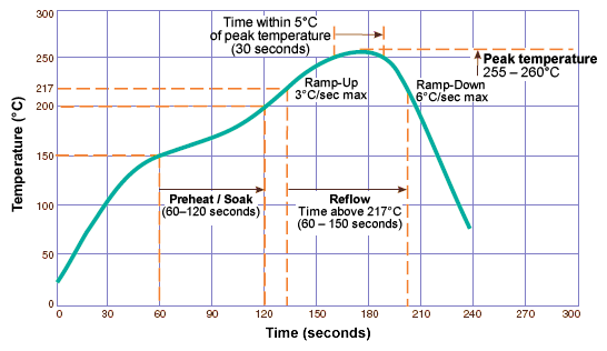
PE: It is easy to think that the most important part of the reflow curve is the maximum temperature of 255°C (480°F). Yes, it is important to build an oven that is capable of reaching those temperatures. However, another important number is the rate-of-rise of temperature at the higher temperatures. At higher temperatures it becomes increasingly more difficult to increase the temperature. You run the risk of damaging sensitive components if the reflow takes too long, and you can create hot spots (damaged components) and cold spots (no solder reflow) if you run the elements full blast.
M: Do you have any advice for people just starting out in electronics?
PE: It is easier than ever before to get started. There is so much information on the internet, and so many open-source projects. What I found to be very helpful was buying a “Getting Started with Arduino Kit” and working through every single example. By the end you’ll be so pumped to design and implement your own projects. Electronics components are incredibly cheap these days.
M: Any tips for working with SMT?
PE: There are many reasons to move to surface-mount technology. Some IC’s are only available as surface mount, their footprint is smaller and assembling boards is faster and easier — with the right equipment. For small boards in low volume, you may be able to use a soldering iron with a very fine tip or a hot air gun and solder paste. But realistically, after doing just a few boards this way you’ll soon be looking for something that does the job quicker and easier — and produces boards that actually work! You won’t regret building yourself a reflow oven, and once you see the results you’ll be designing more complex boards and producing them in higher quantities.
The heat source used for soldering needs to be carefully considered. Most IC’s are designed for lead-free reflow and are certified to tolerate temperatures as high as 260°C (lead-free solder becomes liquidous at 217°C). A hot air gun is likely to exceed this temperature. Some cheaper reflow ovens place infra-red heating elements directly above the boards so dark components absorb more of the heat and end up cooking. Even if the boards still work, the MTBF (mean time before failure) will be compromised.
Use a stencil when applying solder paste. You can use polyimide stencils for small-run prototyping, but stainless steel stencils really do make a huge difference. YouTube is a great source of video tutorials on everything surface-mount.
ADVERTISEMENT


