Hydraulic Robots

Why would you want to use hydraulics on your robot? It was good enough for the car-sized fighting robots Mark Setrakian designed for Robot Combat League, the show he helped develop for the SyFy network. I’m not suggesting you build a giant robot (although that’d be pretty cool), but there is plenty you can learn, and knowledge is power.
Take a look though the concepts below, then I’ll share a hydraulic project idea that’s less… weighty than an 800 lb robot.
Characteristics of Hydraulics
Incompressible!

Image by Orion 8, CC BY-SA 3.0, via Wikimedia Commons
Both pneumatics and hydraulics are systems of pressurized fluids. The key difference is that pneumatic systems deal with gasses and hydraulic systems deal with liquids. Unlike gasses, liquids are incompressible.
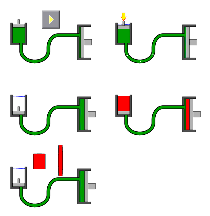
The animation on the right shows a hydraulic system. Because it is a constrained system of an incompressible fluid, the volume of liquid squeezed out of the small cylinder is equal to the volume squeezed into the large cylinder.
Under Pressure
Pascal’s law describes how pressure acts upon liquids confined in a container. In the picture below, the liquid on the left is in an open cylindrical container. The pressure near the bottom will be higher than the pressure at the top, because there is more mass weighing upon the liquid the further down you go.
If the same cylinder of liquid was moved to a higher elevation where atmospheric pressure was 10 kPa less, the pressure near the bottom would still be greater than near the top. However, the pressure everywhere in the liquid would be exactly 10 kPa less than before.

Image by Andrew Terranova
Now if you place a tightly fitting piston on top of the liquid in the cylinder, as in the cylinder on the right, something interesting happens. Since the liquid is incompressible, the pressure now equalizes throughout the liquid, and applies a force equally to all points of its container.
Taking Mechanical Advantage
A consequence of all this is that you can get a mechanical advantage. When you apply a force to the small cylinder, the amount of force exerted by the large cylinder is proportional to the ratio of the surface areas of the two cylinders.

Image by Rahulgoel12345 CC BY-SA 4.0, via Wikimedia Commons
In other words, you apply a small force to the small cylinder, and you get a large force on the large cylinder. You may be familiar with this principle if you have ever used a hydraulic car jack or log splitter.
There is an inversely proportional effect on distance… you have to move the small cylinder a long way to make the large cylinder move a short way. This is analogous to using a block and tackle pulley system to lift a large weight. You have to pull the rope further than the distance you lift your intended load, but you don’t have to pull as hard.
Building a Hydraulic Arm
Now that you have some of the theory, let’s look at a practical example you can build yourself.
Assemble the Kit
I picked up this inexpensive hydraulic robot arm for my son, which helped inspire this post.
As you can see in the video, when you move any of the three syringes at the control end, the water pushes the syringes integrated into the arm’s actuators.
The syringes in the kit are all the same size, so the force applied and distance moved is the same.

Image by Andrew Terranova
If you wanted to lift a heavier load with the robot arm, you could substitute a larger diameter syringe into the lift actuator. You would not be able to move the arm as far, but it could now lift more weight. You would have to change the corresponding control syringe for a longer one of the original diameter to try to maintain the same distance on the output.

Image by Andrew Terranova
Add Some Actuators
For some bonus points, I’m working on adding a linear actuator to each syringe.

You can build your own linear actuator from a modified servo and an old glue stick. I found that a short length of schedule 40½” PVC pipe can be glued into the glue stick base of the actuator, and the plunger of the syringe makes a good friction fit into the other end of the pipe.
Once assembled, your inexpensive hydraulic robot arm can be programmed with a microcontroller.
ADVERTISEMENT


