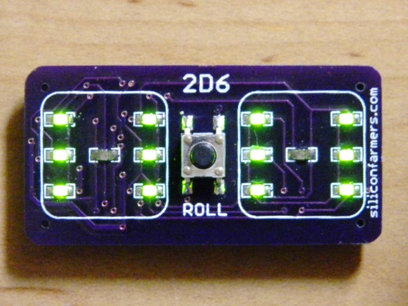
You will end up with a 2-dice simulator that can be used for games and fun, and satisfaction in your new-found knowledge that you gained in the world of SMT electronics.

Project kits and support at AE9RB.com.

What will the next generation of Make: look like? We’re inviting you to shape the future by investing in Make:. By becoming an investor, you help decide what’s next. The future of Make: is in your hands. Learn More.

Project Steps

Learn to solder SMT

Read the manga. This guide assumes you have the knowledge contained therein.

An Italian translation is also available.

Solder fourteen LEDs to the top of the board.

The LEDs have a green triangle on the underside of the part. The LED’s triangle direction should match the silk screened triangle at each LED location.

These LEDs are 0805 in size. That means 0.08 inches by 0.05 inches. (~2.0×1.25mm)

On the bottom of the board, solder the six 27 ohm resistors in locations R0, R1, R2, R3, R5, R6.

Leave R10 empty if your board has pads for it. It was intended for a 10K pullup, but we just use the internal resistor of the ATtiny13.

Solder the 10µF capacitor at C2. This is a 1206 sized part, which is larger than the other 2-pin parts.

We are using a ceramic capacitor for C2, so you don’t have to worry about polarity. It can go on the board either way.

Solder in IC1, the ATtiny13. It comes pre-programmed with the code to roll the dice. Note that pin 1 is indicated on the part with a small circle. This pin will go where you see a corresponding small circle in the silkscreen.

Page 14 of the comic shows how to solder an SMT IC.

Solder the 0.1µF capacitor at C1 near IC1. C1 is the only 0805 part that you only get one of.

Put a bump of solder on the center pad of BAT1. This helps the battery terminal to make contact with the board.

Place the battery holder in position on BAT1. Heat one pad and apply solder. The solder should wick onto the pin of the battery holder.

Solder the other side of the battery holder.

Apply the rubber feet. They are self-adhesive. Peel and stick.

Flip the board back to the top. Solder the pushbutton, which goes on the four large pads just above the word “ROLL”.

Use the same technique you used for IC1.

If you have an ohm meter, check across C2 to see if there is a short. Your meter should show the same reading as when the probes are touching nothing — infinite ohms.

Insert a CR2032 battery. The + side goes away from the board.

The LEDs should light up two at a time, and finish with all 14 LEDs lit. Pushing the button at any time will roll the dice. If the button isn’t pushed for about 30 seconds, the LEDs will go off to save power.

The battery will last about a month. To preserve the battery power, remove it when you finish using the dice for the day.