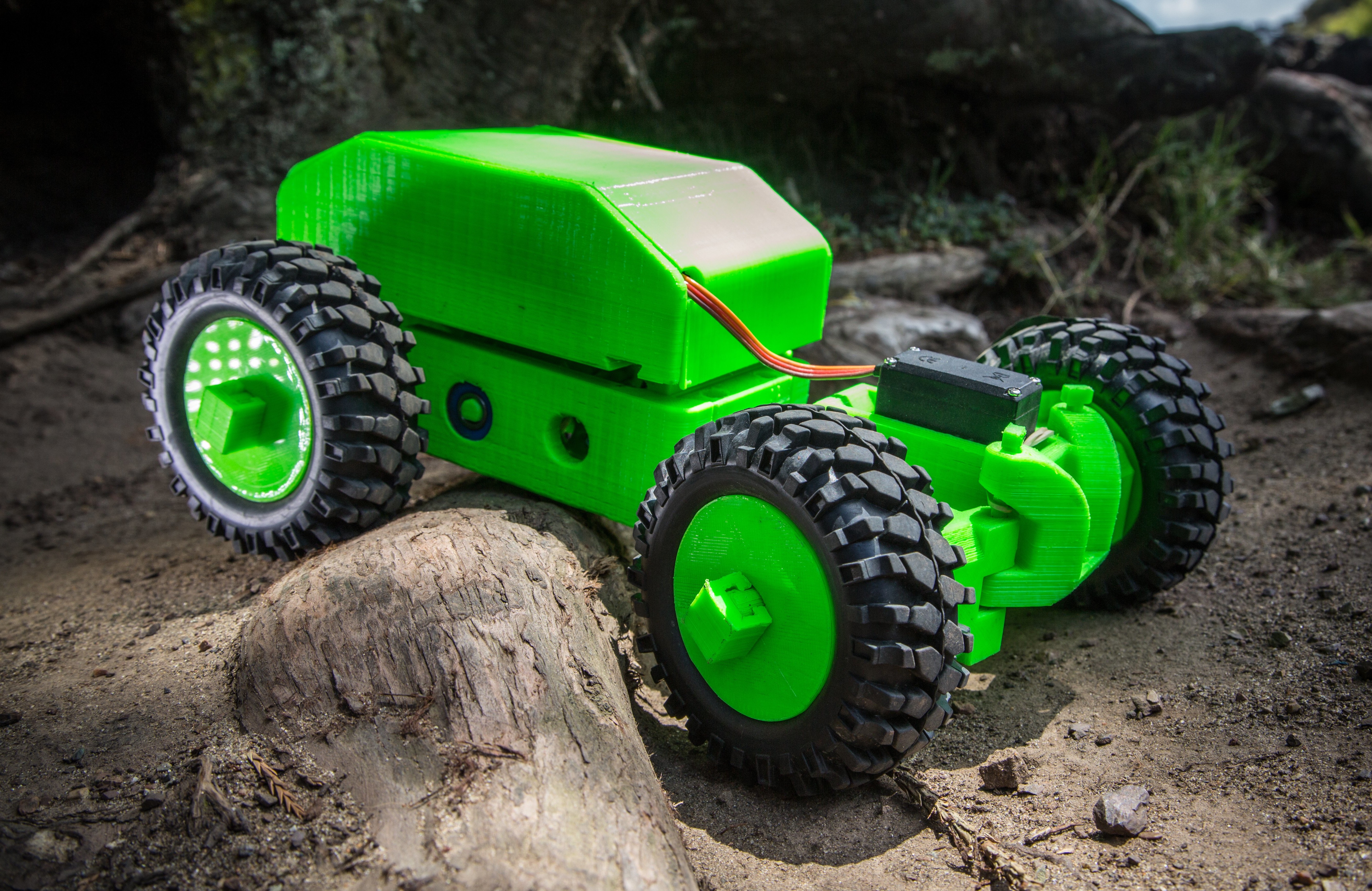
FlutterScout-30
Photos by Taylor Alexander

[Editor’s note: We loved this project so much, we’ve brought it back with complete steps so you can follow along while making your own!]

3D printers, I think, are a bigger deal than most people realize. For the first time in human history, we have a way to produce high-quality, complex parts at nearly zero marginal cost. Case in point: This 3D printed race car only requires $10 in material, 24 hours of machine time, and $1 in electricity. If the machine could be fed with industrial plastic pellets instead of custom-made filament, it would only be $1 in plastic.

I worked for 7 years designing parts and programming industrial CNC metal cutting machines in a machine shop, so I know well how much labor it typically takes to produce a good part. A CNC machine has many automatic features and makes very high-quality parts, but it still takes a lot of skilled labor to use. 3D printers, on the other hand, take no labor at all to produce complex parts. That’s a very new thing, and has the potential to do for mechanical goods what the printing press did for books — eliminate essentially all human labor required to make things, and drastically lower the cost of living.

Our society runs on the idea that physical resources are scarce, but what if we could end that scarcity? What if we could print robots that could do all the hard work in society? All the farms, shipping depots, kitchens, mines, hospitals, and factories in the world could be run for the cost of sunshine and some basic materials. With such a system in place, the cost to support a human life would drop to zero, and people would no longer need to work to survive. Is such a world possible? It may be a long way out, but I believe it’s possible.

I wanted to inspire people to use 3D printers to build real robots, so I built this car — I call it the Scout — to show off some of the 3D-printed robotics concepts I’ve been developing. First, the car isn’t a weakling. It can take repeated jumps and crashes with no damage. That’s important to show people that this works in the real world, not just on a workbench. If it does break, it’s easy to repair in minutes, thanks to its snap-together design. And the design is open source, so it can mature over time and inspire new variants. It uses a minimum of non-printed parts — only the tires, bearings, motors, batteries, and electronics — and it doesn’t even use screws, because they aren’t necessary and would only add complexity. (Plus, shunning screws makes it a harder problem, which I like!)

Ultimately, the 3D printed Scout is part of a broader robotics construction kit I am building. The wireless radio in the car and remote is my own design — a board called Flutter. Flutter runs Arduino code and has a built-in wireless radio with 1-kilometer range. Since it runs Arduino, the car can be modified with lights, sensors, speakers, and more. I plan on adding an OLED display to my remote control to show me telemetry data on the car like speed, RPM, and battery level. Beyond the wireless boards, I hope to develop motor control and battery management boards for robots as well, so that one coherent open source system can be used to build almost any robot.

Assembling the Scout car is easy, and only takes a few minutes. Printing the parts, however, is still a real commitment. Currently it’s over 24 hours of print time, though I think it could be done in under 10 hours with a large-nozzle 3D print head like the E3D Volcano.

What will the next generation of Make: look like? We’re inviting you to shape the future by investing in Make:. By becoming an investor, you help decide what’s next. The future of Make: is in your hands. Learn More.

Project Steps

Print the parts

Most of the Scout’s parts can print on a 150mm × 150mm build surface, but the 2-part electronics housing is currently 156mm long. I recommend printing with PLA on a heated bed.

Download the parts and get printing. There are detailed instructions there, but basically most parts can be 20%–30% infill, while gears, drive shafts, and steering pins should be 100% infill. Print the parts for the front end first, and note that the electronics bay and cover may need to be printed with a “brim” for extra adhesion.

Test the electronics

Solder connectors onto the ESC for the motor and the battery, and cover all connections with heat shrink tubing. Lithium batteries have a lot of power, and short circuits can be dangerous.

Follow the instructions that came with the Flutter kit (or your radio) to attach the servo and speed controller, and then power everything up and make sure it works.

Assemble the front end

The front end consists of 2 wheel assemblies and the center frame. Place the bearings and drive shaft into each bearing assembly and slide in the shaft cover.

Then for each wheel assembly slide on 2 hub plates and a tire, and secure them with the wheel shaft clip.

Assemble the front end (cont'd)

Next, take the servo (with the “horn” removed) and slide it into its cavity in the frame, first forward at a 45° angle and then down, so that the front of the servo locks underneath the lip in the front of the cavity.

Secure the servo by sliding a steering pin through the small hole in the frame member above the servo flange, and flip over the assembly.

Attach the 6-lobed servo horn to the servo, capturing the steering rack beneath it. If your servo didn’t come with a 6-lobed horn, a printable version is in the Github repository.

Attach the wheels

First, wrap the rubber band around the top steering towers, and attach the wheel assemblies using the short and long pins.

Then bring the front of the rubber band back over the steering towers.

The rubber band isn’t critical, but helps to keep the long steering pins from working their way out.

Power up the servo and make sure everything is centered. If the servo isn’t centered when powered on, just unscrew the servo horn and adjust the position until the steering is straight.

Assemble the rear end

The rear frame holds the motor and the drive shafts. Start by collecting the pieces needed for the small, middle drive shaft.

Install the gears on both ends of the shaft with the large gear on the longer end. Place one 608 bearing on the end of the shaft by the large gear, and the other 608 bearing in the frame. Guide the bearing on the shaft into its hole at an angle, then straighten out the shaft and place the short end into the opposite bearing.

Secure the shaft with the 8mm shaft clip, aligning the flat inside the clip with the small notch in the middle drive shaft.

Assemble the rear end, cont'd

Now you’ll assemble the rear drive shaft and install it into the frame. Take the large, rear drive shaft and install the rear drive gear so that it mates with the rectangular section of the shaft, and then place 12mm bearings on both ends of the shaft. Lower the shaft into the frame so that the large rear gear mates with the small middle gear, and then slide the bearings into their recesses.

Snap the 12mm shaft clip onto the rear shaft.

Install the motor

Assemble the motor, small drive gear, and quadcopter propeller adapter as shown here.

These adapters were designed to turn only one direction, but our car spins the motor both directions, and the gear can loosen if it’s not tight enough. So use the simple 3D printed wrench to hold the gear while tightening the adapter with pliers. It should be pretty tight, but be careful as these aluminum propeller adapters can break with heavy tightening.

Now slide the motor into its hole in the rear frame with the wires facing up, and then lock it in place with the motor lock wedge.

Install the motor, cont'd

You should now have something that resembles a giant servomotor.

Final body assembly

Slide the front end assembly onto the large dovetail in the rear frame. Then slide the electronics bay over the top, with the motor wires feeding into the side hole.

Center the electronics bay over the rear frame, and drop in 2 short pins.

Install the electronics

If you sourced the recommended parts, they just drop into place. Remove the power switch from the ESC, feed it through the power switch hole, and then plug it back into the ESC.

Next, plug the motor leads into the ESC. There are 3 leads and they can be plugged in to the ESC in any arrangement. If the motor spins backward, switch any 2 wires and you’ll be good.

Hook up the servo wire and the speed controller to the radio, and then plug in the battery and neatly stow all the wires.

Build the remote (optional)

Just plug the Flutter module and the battery into your Remote Control Board, and then snap it into the 3D printed controller housing.

If you’re using your own R/C gear you can skip this step.

Close it up and drive!

Snap on the lid and you should be ready to roll. Go outside and test Scout’s limits. Scout is fast and loves jumps. And if you break anything you can always print more parts!

We’d love to see people tweet pictures of their own Scout builds to @FlutterWireless. And if you want to talk to others about assembling Scout or about new design ideas, please visit our online community.