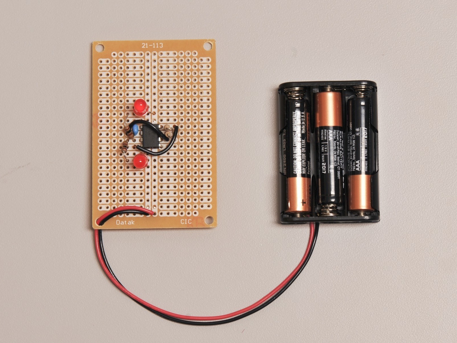
In this project, you’ll learn how to solder together a battery-powered, 555 Timer-driven blinky toy.

What will the next generation of Make: look like? We’re inviting you to shape the future by investing in Make:. By becoming an investor, you help decide what’s next. The future of Make: is in your hands. Learn More.

Project Steps

Make sure you have two LEDs, a 555 timer, a capacitor (between .1 µF and 1µF), the four resistors shown (2x 1 megohm, and 2x 100 ohm) , and a battery box. You’ll need to supply a small amount of hookup wire.

Place the protoboard in the helping hands in the orientation shown here.

To solder each component, you’ll keep the board in the helping hands and roll it over, away from you so that it’s reversed and upside down.

In this guide, we’ll show the top view of the board on the left and the reversed view of the board on the right.

Place the 555 timer into the protoboard as shown, paying attention to the notch in the 555 timer (it should be pointing up).

Flip the board over and solder the pads shown on the right-hand side of the image.

Place the 1 megohm resistor (Brown, Black, Green) into the board as shown.

The orientation of the resistor doesn’t matter.

Flip the board over and solder the resistor into place. Trim the leads when you’re done.

Place the second 1 megohm resistor into the board.

Flip the board over, solder the resistor in place, and trim the leads.

Insert the capacitor into the board as shown.

Like the resistors, the orientation of this kind of capacitor doesn’t matter.

Solder the capacitor into place and trim the leads.

Prepare a short length of red hookup wire. This wire will be hooked up to the positive side of the battery and provide power to the chip.

Cut it so it’s a little longer than the length shown.

Strip the ends to about 1/2 an inch.

Tin the ends of the wire.

Insert the wire into the board as shown, flip it over, and solder it into place. If you have any excess, trim it.

Prepare a length of green wire (or blue or yellow) as shown.

Insert it into the board as shown.

Solder it into place and trim any excess.

Insert a 100 ohm resistor as shown.

Solder it into place and trim the leads.

Insert the second 100 ohm resistor as shown.

Solder the resistor into place and trim the leads.

Insert the LED as shown.

You must orient the LED as shown. The long (positive) lead needs to be on the side marked with the + symbol and the short (negative) lead on the side with the – symbol.

Solder it into place and trim the leads.

Place the second LED into the board.

The long (positive) lead needs to be on the side marked with the + symbol and the short (negative) lead on the side with the – symbol.

Solder it in place and trim the leads.

Prepare another length of red jumper wire.

Place it in the PCB as shown.

Solder it into place and trim any excess.

Connect the battery box and blue wire as shown.

Remove the batteries before you solder it into place.

Solder the battery box and blue wire into place and trim away any excess wire.

Connect the battery and watch it blink!

The LEDs blink in an alternating fashion because one is connected “backwards”. When the 555 timer’s output pin goes “low”, electricity flows through that LED. The other LED is connected normally.