YouTube player

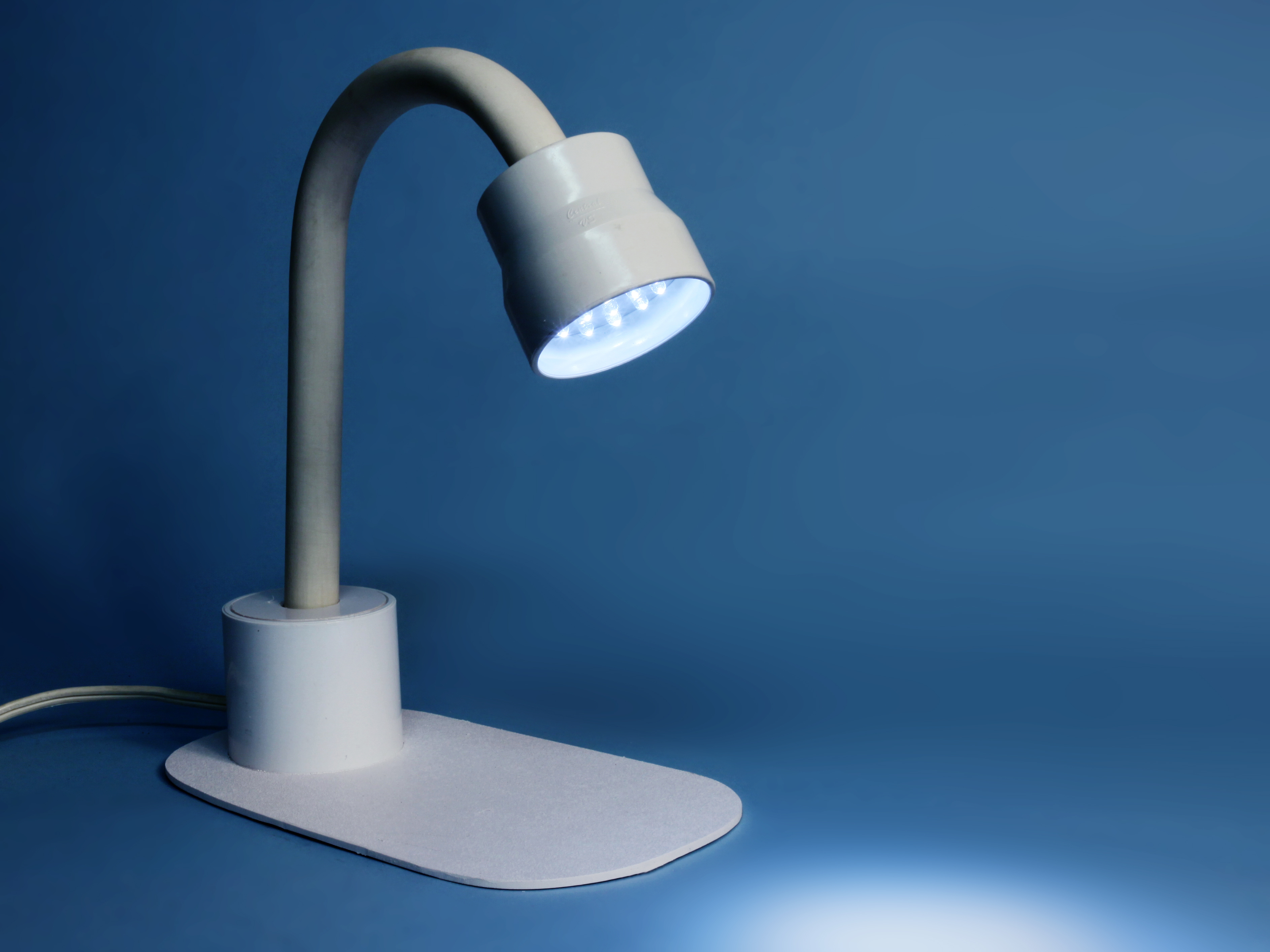
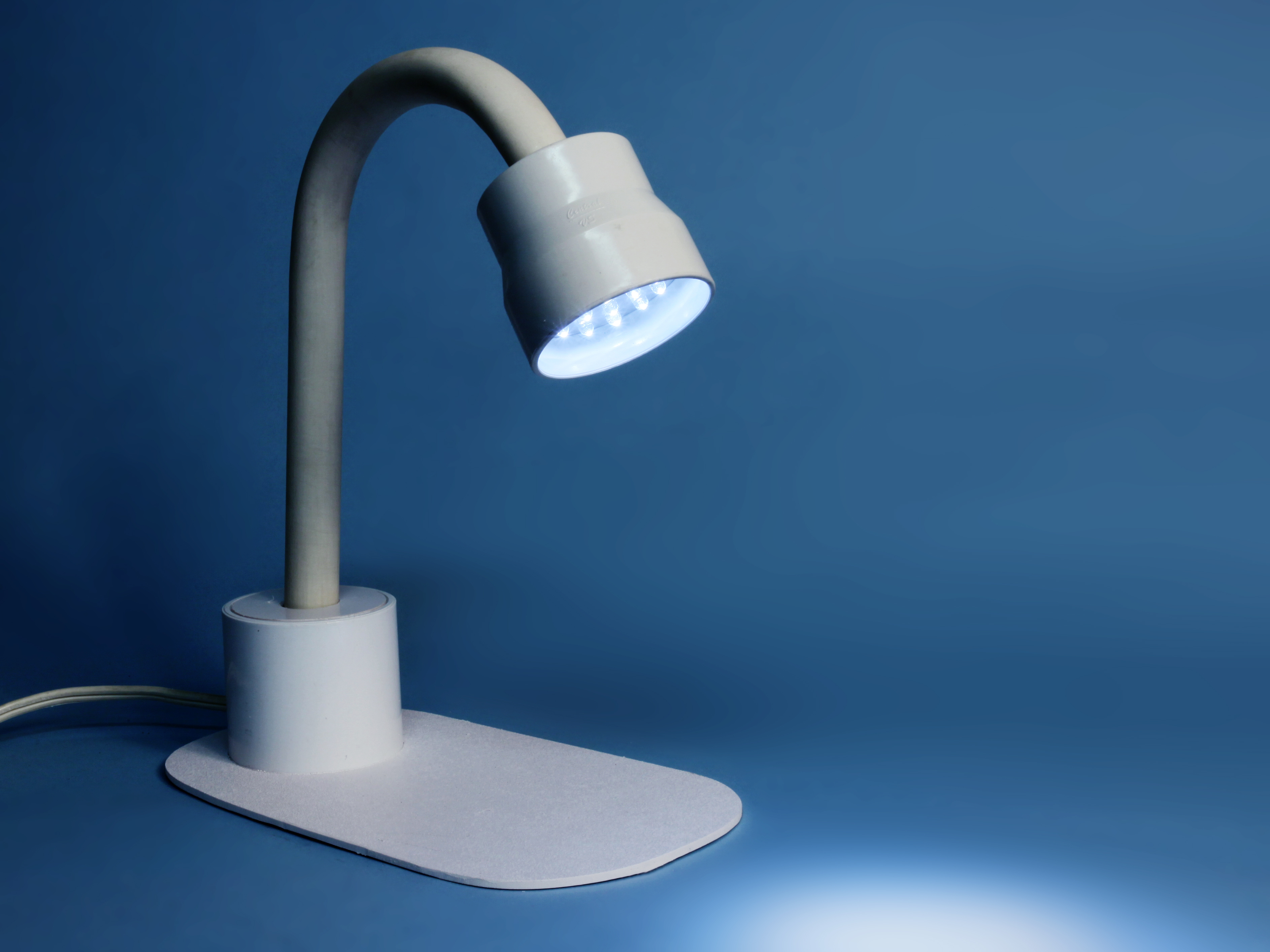
The most popular item I ever built for MAKE just happened to be the simplest: an LED desk lamp. This was in Volume 08, in 2006, when white LEDs were a hot new product. The most powerful ones I could find were 1cm in diameter, rated to deliver 100,000mcd (millicandle). The light wasn’t exactly white — it had a freaky purplish hue. But I liked the weird color, because it showed we were early adopters of cutting-edge illumination!

Recently I started wondering if I could downsize and upgrade the original lamp. So I took a fresh look at those traditional, through-hole, single-component LED “indicators” (as they are properly known).

The 5mm ones are now a lot more powerful than the 1cm type I used in the past. Some of them, known as “5-chip,” have 5 light-emitting elements squeezed into one 5mm package, sucking down 100mA of forward current at around 3.3V DC.

They’re still rated at 100,000mcd, but 6 years ago, the ones I used were rated for only 20° of beam spread. Today’s 5-chip LEDs claim a spread of 60°. Does that mean they’re 3 times as bright? No, they should be 9 times as bright, because the light is delivered over a two-dimensional area!

Since I used 72 of the big old ones, and the new ones should be 9 times as bright, I would only need 8 to get the same illumination. But why not go for greater output?

Here we’ll use the traditional-style 5mm LEDs. RadioShack, for instance, offers them as part #276-017. Since they use exactly the same 3.3V DC as the 5-chip variety, you can substitute either in this project without changing the circuit.

Fabrication Choices

I opted for a 12V DC power supply, to make the lamp function in motor homes, where LEDs are ideal to conserve power. For use with 115V AC, you need an adapter that delivers 12V DC at 1 amp. Here we’ll use RadioShack part #273-358.

Instead of adding a series resistor with each LED, the most efficient way to power them from 12V DC is by series-wiring them in threes. This means you need 10V DC for each set. How to get 10V from 12V power? Pulse-width modulation is the way to go. You send a stream of pulses, too rapid for the eye to see, and vary the gaps between them to limit the average current. If you add a potentiometer, this can act as a dimmer. Only a few electronic parts are needed, and they’re listed in the materials and specified in Step 5.

Note that if you use old-style low-power LEDs, your AC adapter can be down-rated to 300mA, which should cost less.

How to build the actual lamp? I decided to use PVC plumbing supplies. For the additional pieces that would hold everything together, I chose 1/8″ white ABS plastic, but you can use plywood if you prefer.

Project Steps

Make the lamp head.

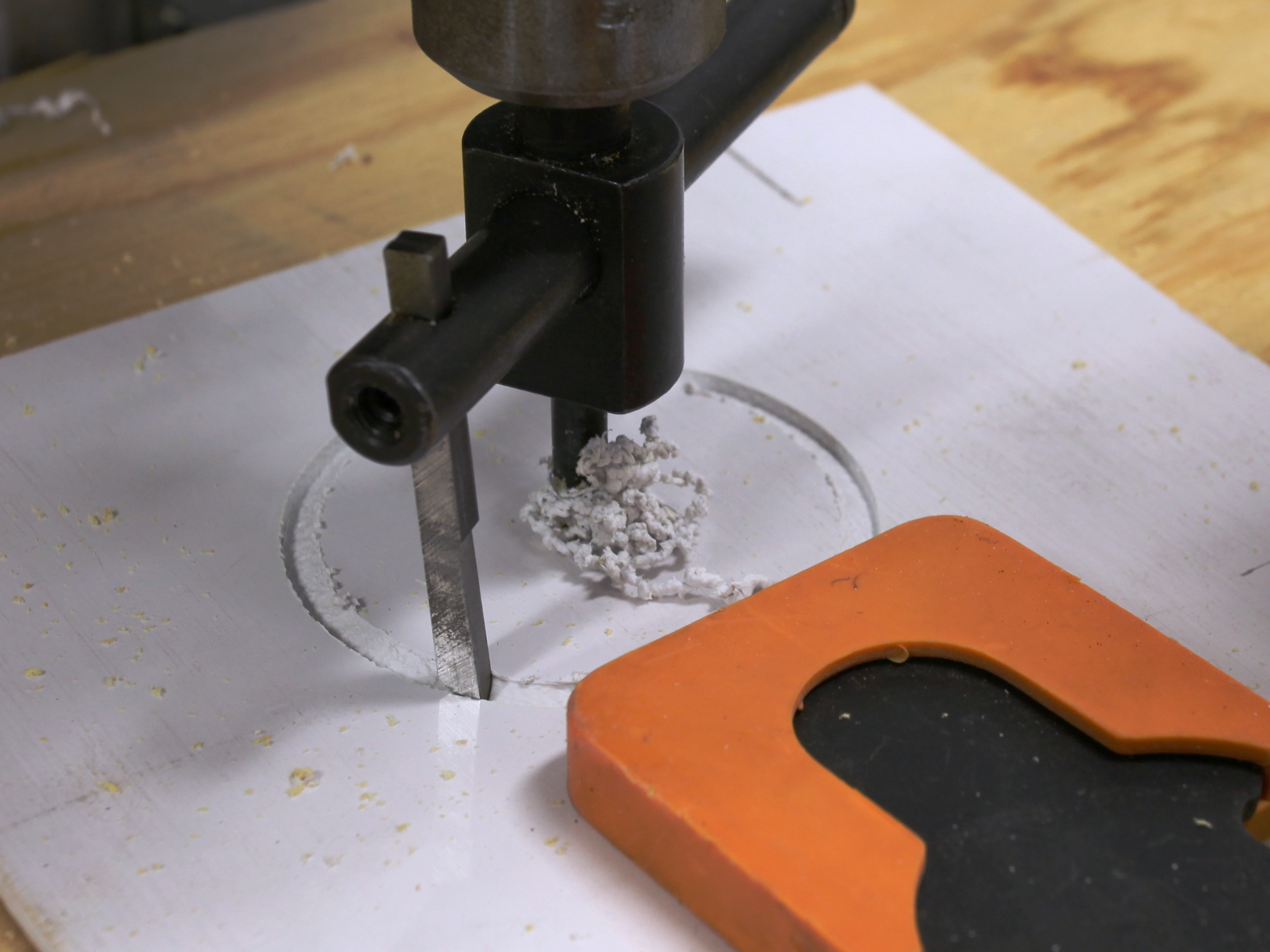
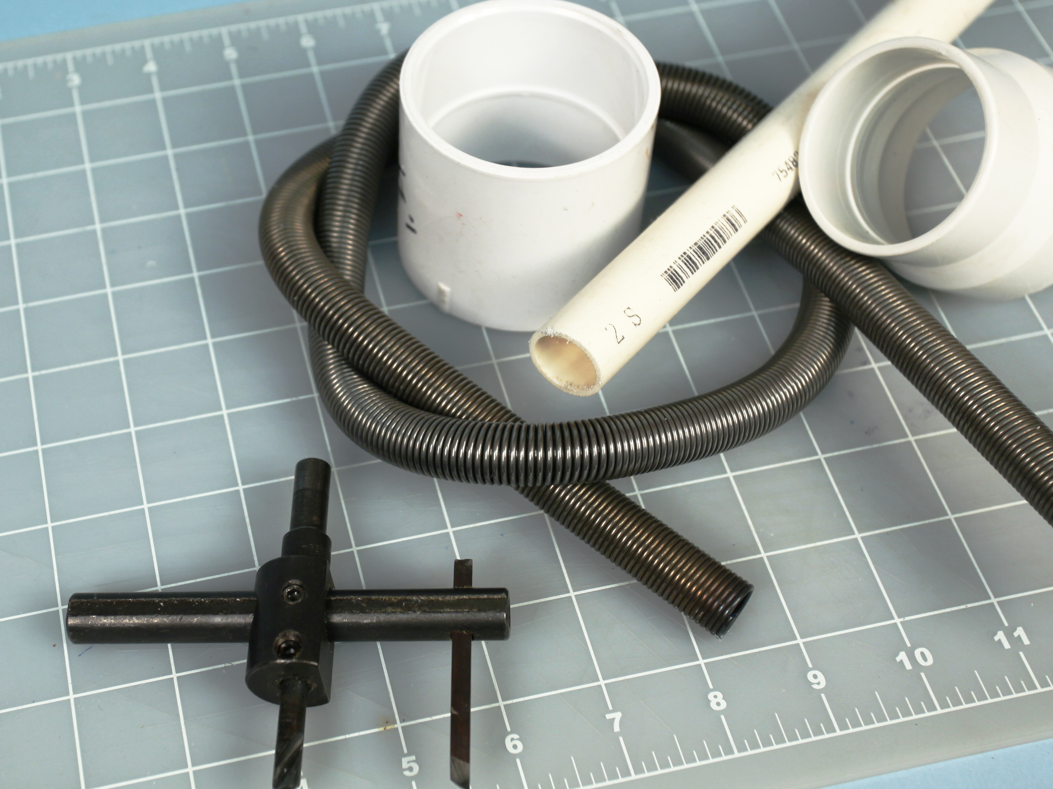
You need an adjustable hole cutter to cut a circle of ABS (or plywood) the same size as the template. They’re $10 on eBay, but to use it safely, you need a drill press, as shown here. Otherwise, use a handsaw and sand the corners to make a circle.

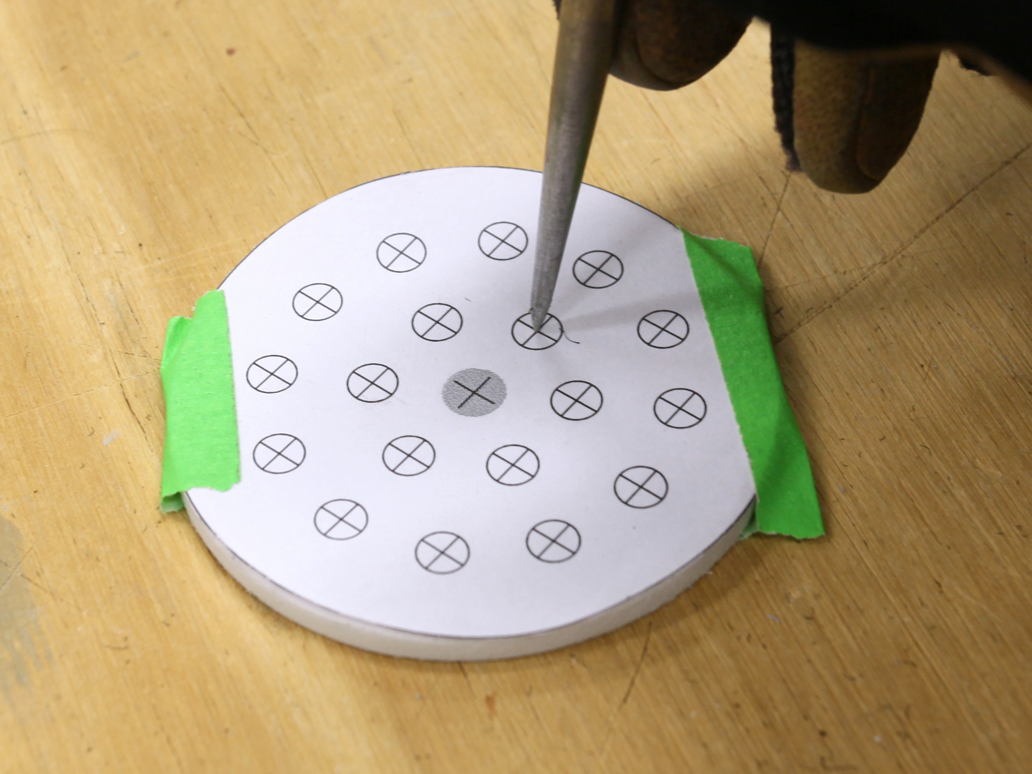
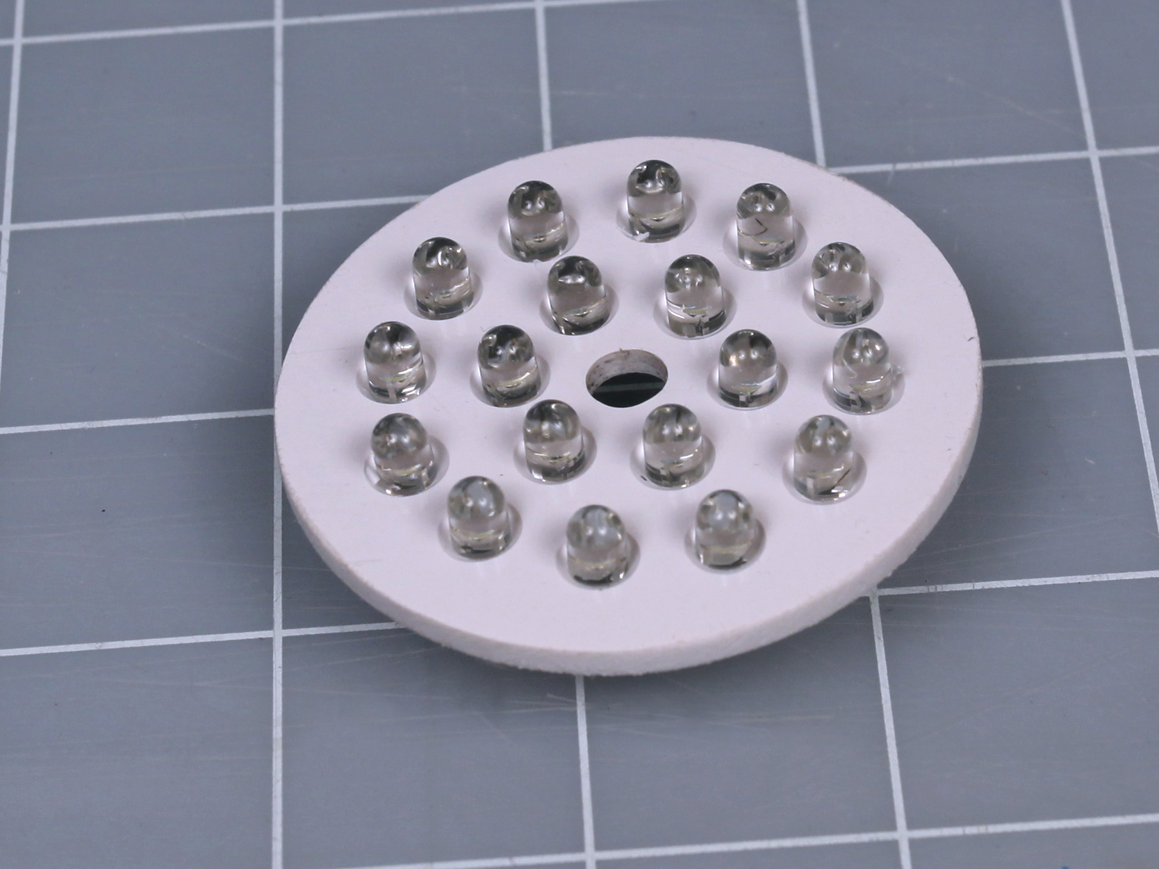
Tape your template to the circle, and use an awl to poke through the center of each hole. Remove the paper and pilot-drill through each indentation with a 1/16″ bit, then drill with a #9 bit. This is the perfect size, and the LEDs will push-fit into the holes, with no glue needed.

Installing the LEDs.

Trim the leads of the LEDs. Make the long leads 1/2″ and the shorter ones 1/4″, so you can still tell them apart. Push the LEDs into the holes, being very careful to get the polarity right.

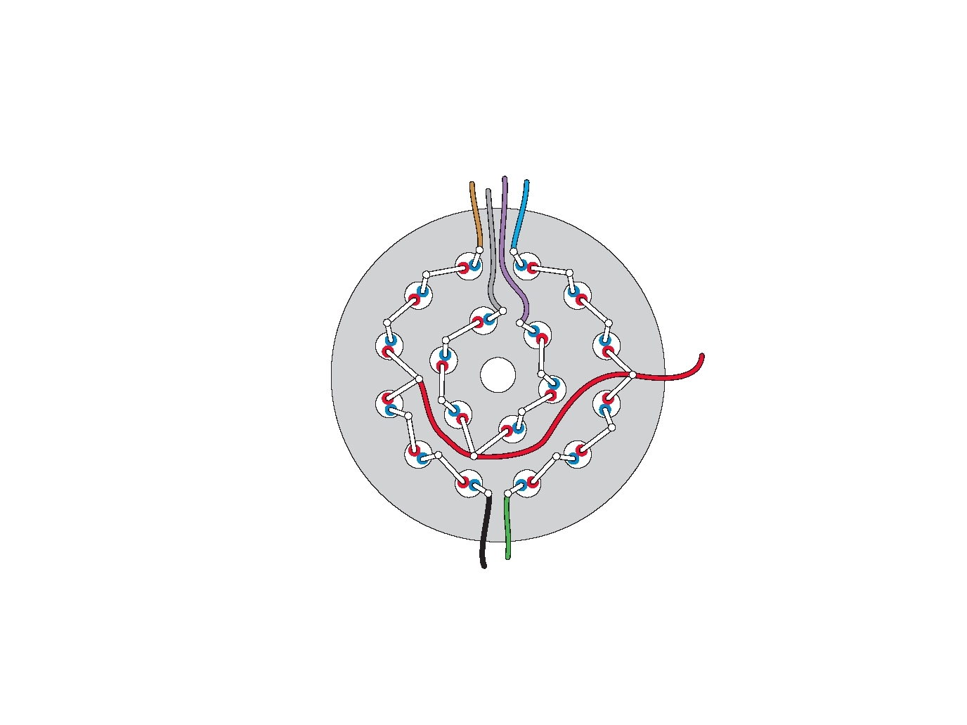
Solder the LED leads together and add wires, as shown. I used a separate wire for each group of 3 LEDs in case I might want to light some of them selectively in the future. The red wire powers the positive sides of all the LEDs, while the other wires are negative. Their insulation colors are arbitrary. The front side of the assembly is also shown here.

Test the assembly. Attach the positive side of a 12V DC power supply to the red wire, and the negative side of the supply to your 680Ω resistor. Touch the free end of the resistor very briefly to each wire leading to the LEDs. They should light up in threes. If you made a polarity error, the resistor should protect you from burning anything out.

Epoxy the LED plate into the wide end of the PVC reducer to form the head of the lamp. Set it aside to harden.

Build the lamp.

Water pipe has ugly text printed on it, so you’ll need to sand it off. Alternatively you can use a solvent, but the solvent may dissolve the PVC.

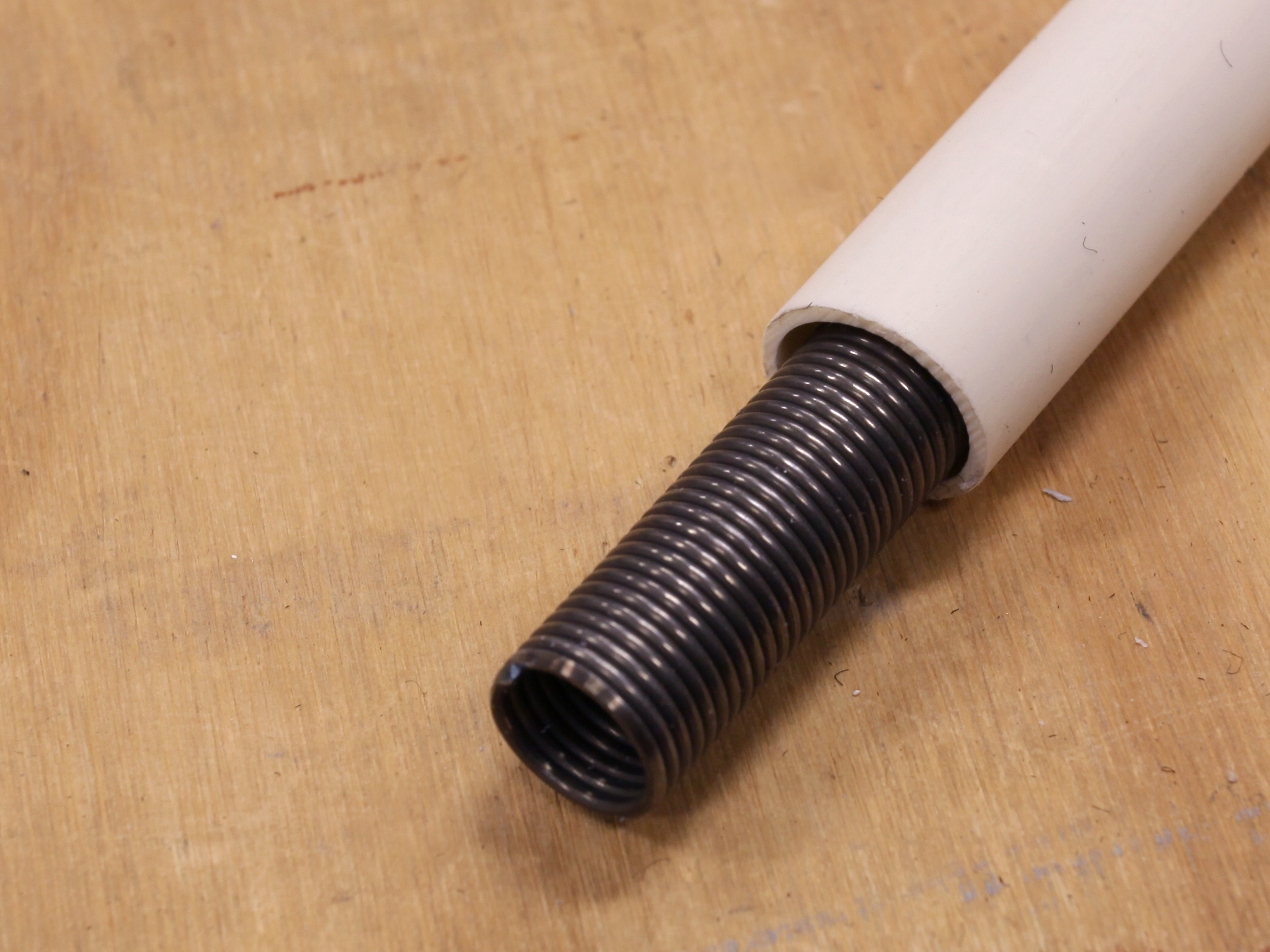
So-called 1/2″ water pipe varies a lot in internal diameter. First measure your pipe, then order a 3′ spring that will fit inside it (as shown in the second image here). The spring will stop the pipe from kinking when you bend it.

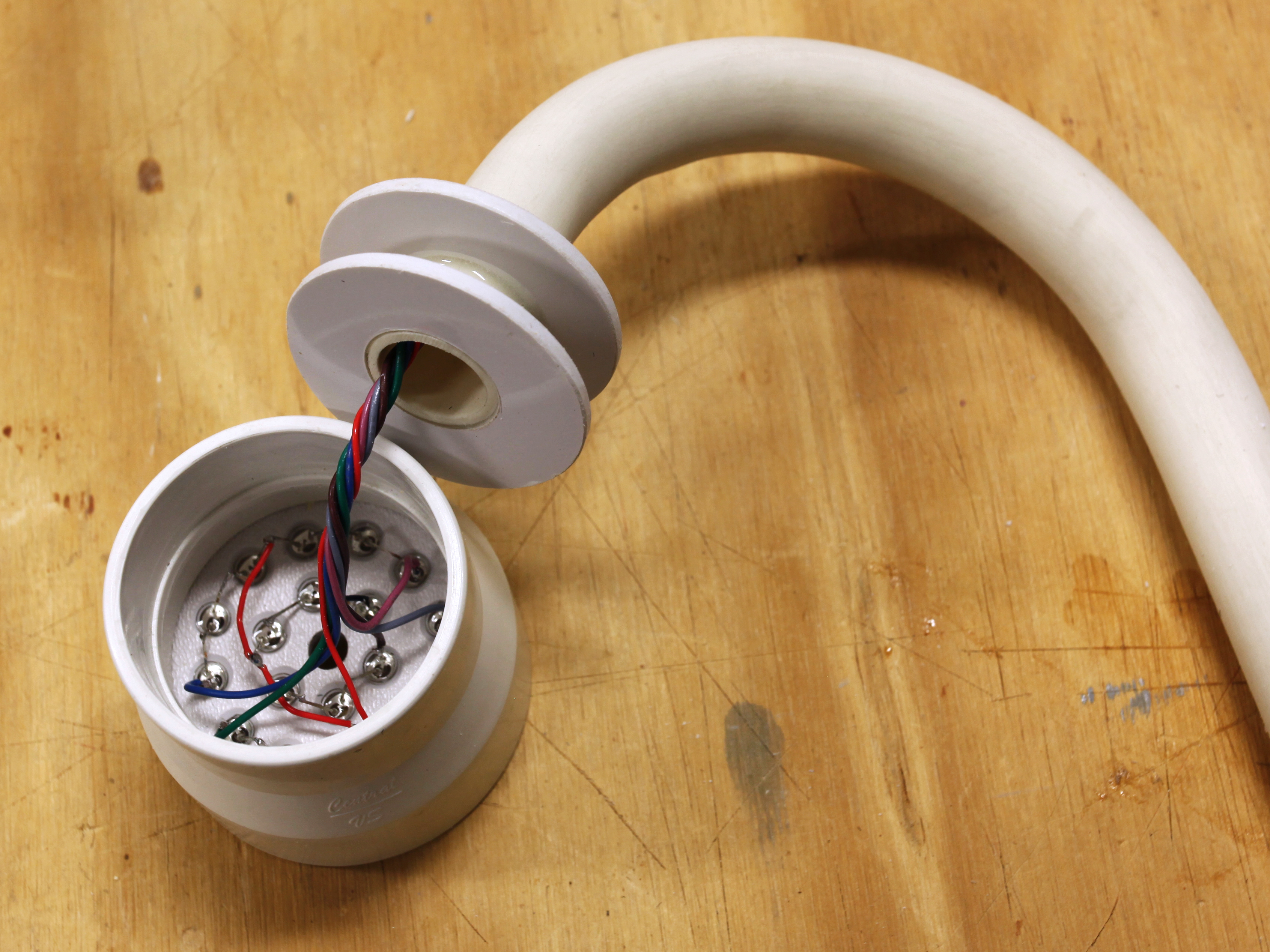
Insert the spring through the pipe and wave a heat gun to and fro along the section that you want to bend, while rotating it. Keep the heat gun moving, and be patient. Eventually the pipe will soften, and can be curved as in the third image here. When you’ve finished, remove the spring and saw the pipe to the size lamp neck you want.

Make the circular base plates.

Make another 2 circular plates to fit the narrow end of your lamp head, and use a Forstner bit to cut holes in their centers to fit the exterior diameter of your 1/2″ pipe.

Epoxy the plates to the lamp neck, as shown here. Thread the wires through the neck, then glue the neck assembly into the head of the lamp.

Next, make 2 more circular ABS plates to fit in the PVC coupling for the base of the lamp, and cut holes in their centers, to fit the ½” pipe.

Epoxy the plates into the base with one halfway down and the other at the very top. Then epoxy the neck into the plates, leaving plenty of room at the bottom for your circuit board and potentiometer.

Breadboard and build the circuit.

For testing purposes, insert a 10uF capacitor for C3.

R1: 4.7kΩ resistor, 1/4W R2: 10kΩ resistor, 1/4W R3: 680Ω resistor, 1/4W P1: 100kΩ linear potentiometer C1: 10uF electrolytic capacitor C2: 0.1uF ceramic capacitor C3: 0.1uF ceramic capacitor (test with 10uF electrolytic) D1: 1N914 signal diode IC1: 555 timer IC2: NTE2013 Darlington array

Using a 12V DC power supply, start with only the components around the 555 timer that are shown in the left half of the schematic, and attach a single test LED between R3 and negative ground. The potentiometer should now adjust the flashing speed of the LED. If not, you made a wiring error.

Remove your test LED and now use R3 to connect the 555 timer to IC2, the Darlington array, as shown in the schematic.

Darlingtons don’t source current, they sink current, so connect the red wire from your LED array permanently to your 12V DC source. Then run the negative return wires into the right-hand pins of the Darlington chip. Its left-hand pins are all driven by the 555 timer. The pins labelled “NC” have no connections.

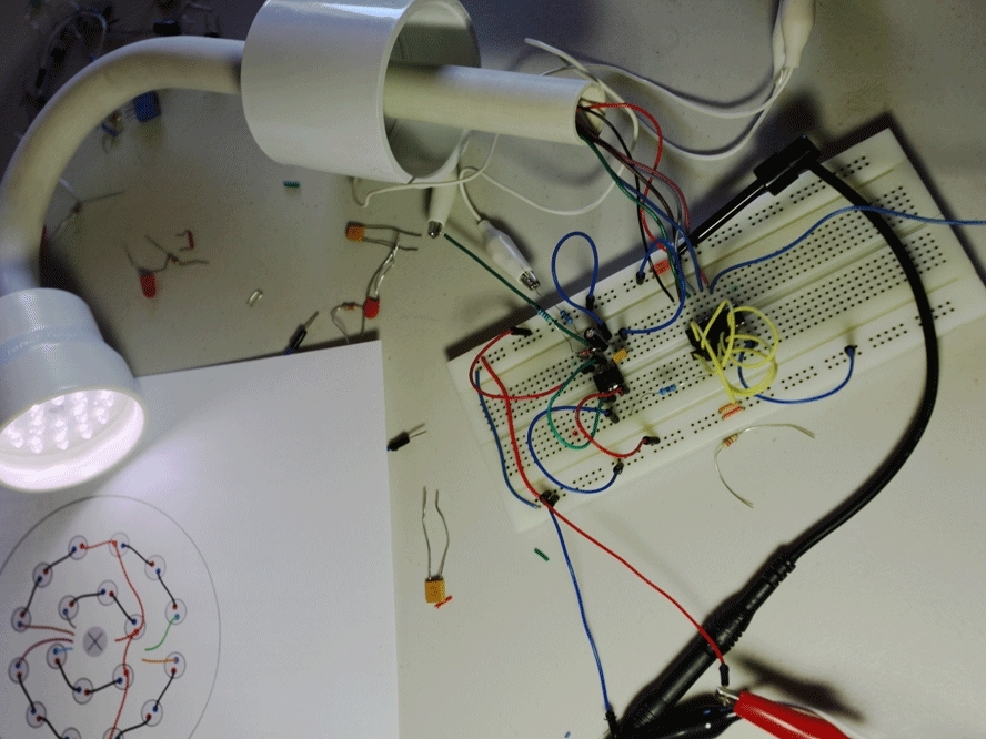
The breadboarded circuit is shown here. If the potentiometer still makes the lights flash faster and slower, all is good.

Remove the 10uF capacitor that you used for C3 and substitute a 0.1uF capacitor so that the lights will flash fast enough to exceed your persistence of vision. Resistor R2 makes sure there is always some “off” time in the pulse train, even when the potentiometer is at the end of its range. This way, the LEDs won’t get overloaded.

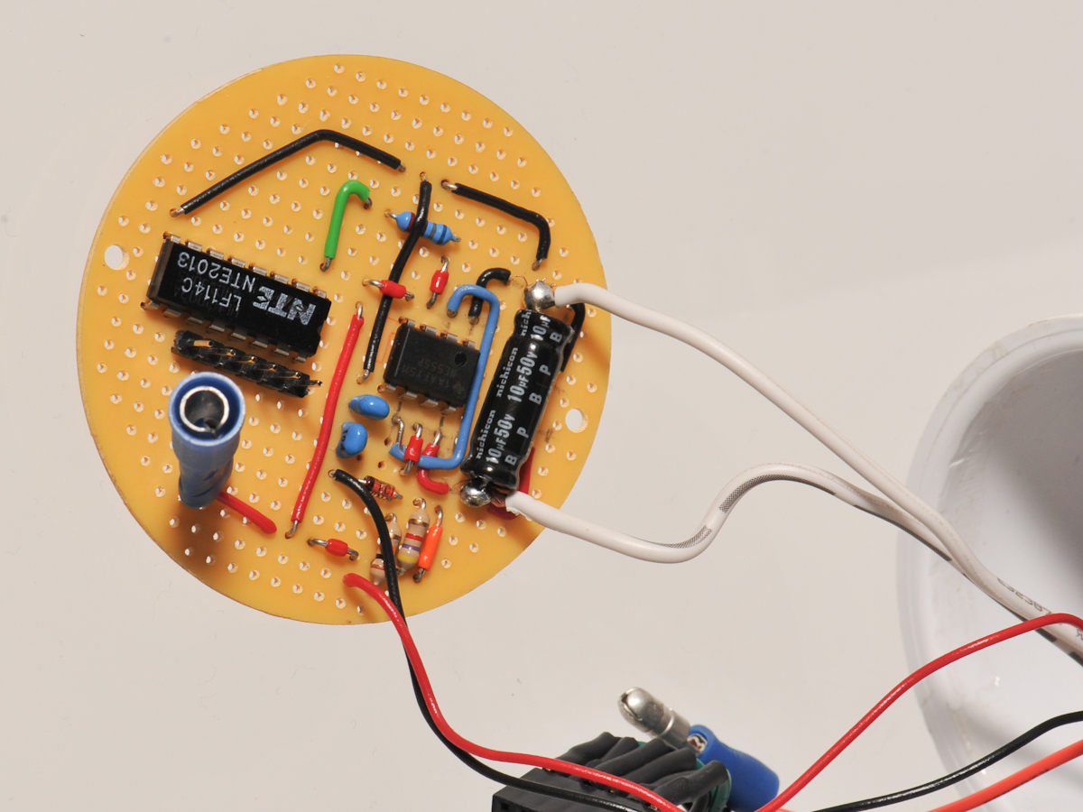
Transpose your circuit to a piece of perfboard and do point-to-point wiring. The largest round PCB from the 5-pack specified in the materials list fits perfectly in the base.

Add power cord and potentiometer.

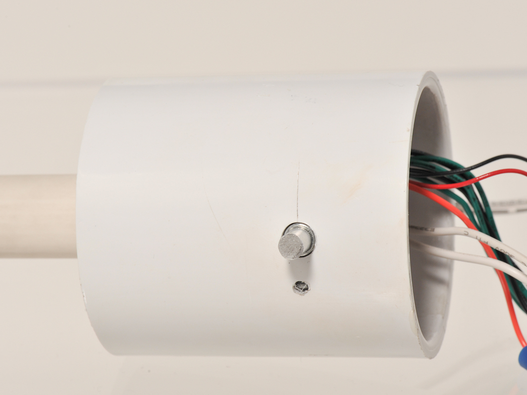
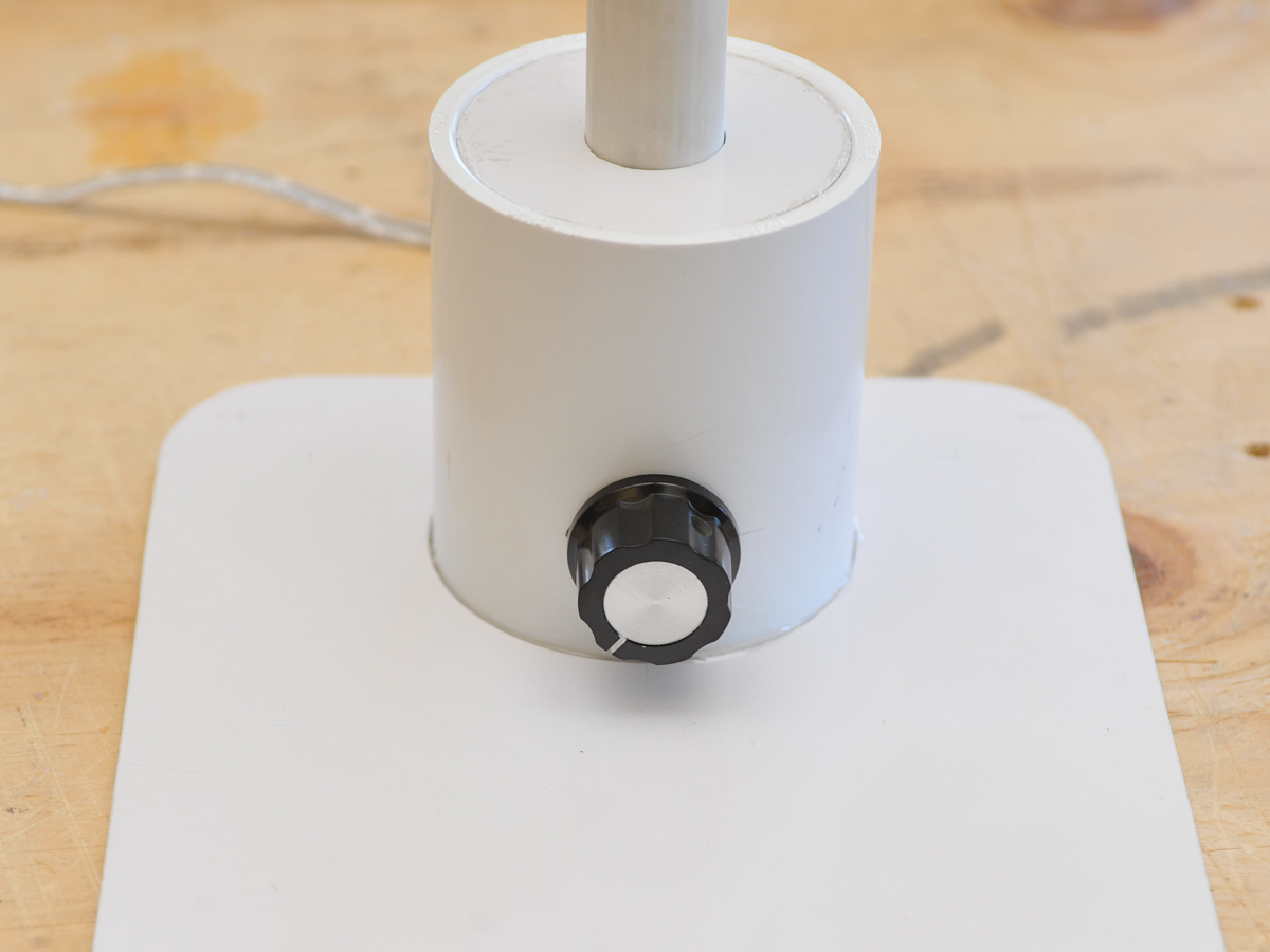
Next you’ll be drilling 3 exit holes: one for the power supply wire, one for the potentiometer shaft, and one for the potentiometer tab. The 2 potentiometer holes are shown here.

For the power cord, drill a 3/16″ hole in the back of the base. Cut the plug off the cord, feed it through the hole, and tie a strain-relief knot inside. You can then solder it directly to the perf board.

Depending on where you prefer the knob to be, you can drill holes for the potentiometer either in the front or back of the base. Use a 21/64″ bit to drill the hole for the shaft, then insert the shaft, mark where the tab goes, and use a 1/8″ bit to drill a small hole for the tab.

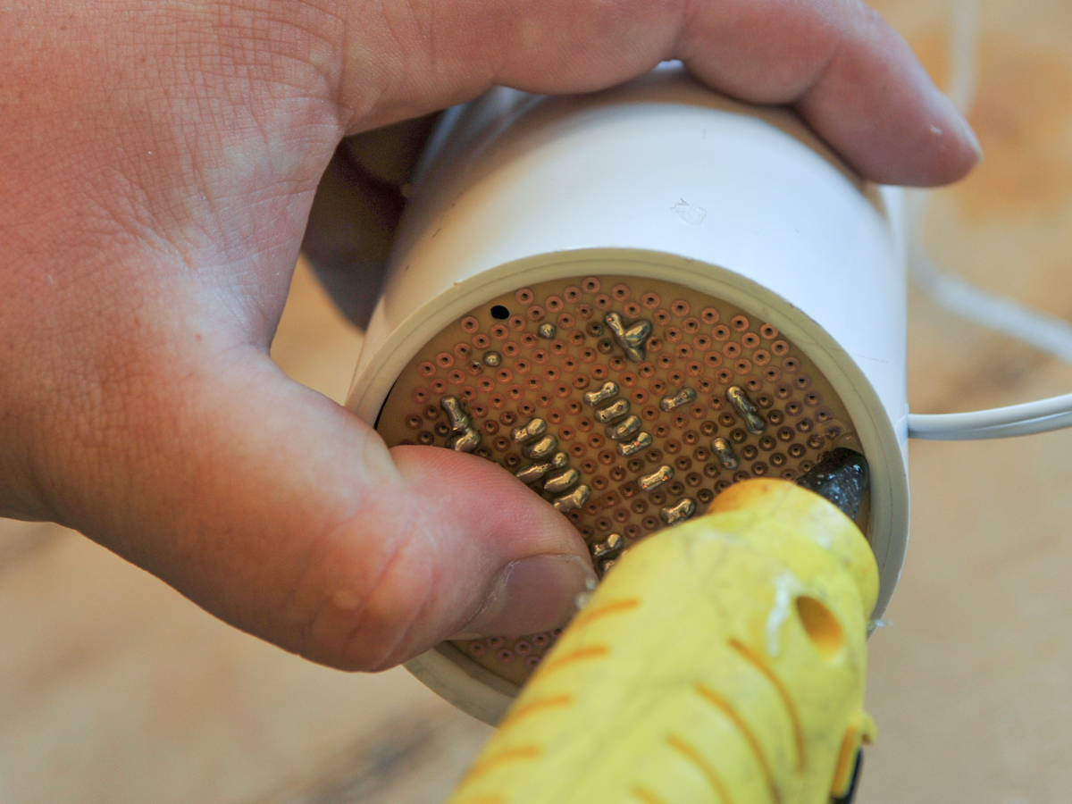
Mount the circuit in the base of the lamp using either a few dabs of epoxy or hot glue.

Add a base.

You’ll need a heavier base, or an extra piece of plastic, to keep your lamp from falling over. I opted for a piece of plastic, but a hollow base might be more convenient, and can be weighted with scrap metal.

If you use plastic, mark where you want the lamp to sit, then use the circle-cutting tool to cut the base out. Use epoxy to affix the lamp to the base.

Enhancements

If you sanded the neck of the lamp, it will be slightly rough and will attract dirt. You could paint it with polyurethane to give it a glossy finish.

Your lamp is complete — for the time being, anyway. Another six years from now, you may be able to build an even smaller version, replacing the 18 LEDs with just one.

Either way, the freaky purplish hue that those big old 1cm LEDs emitted back in 2006 will be nothing more than a memory.