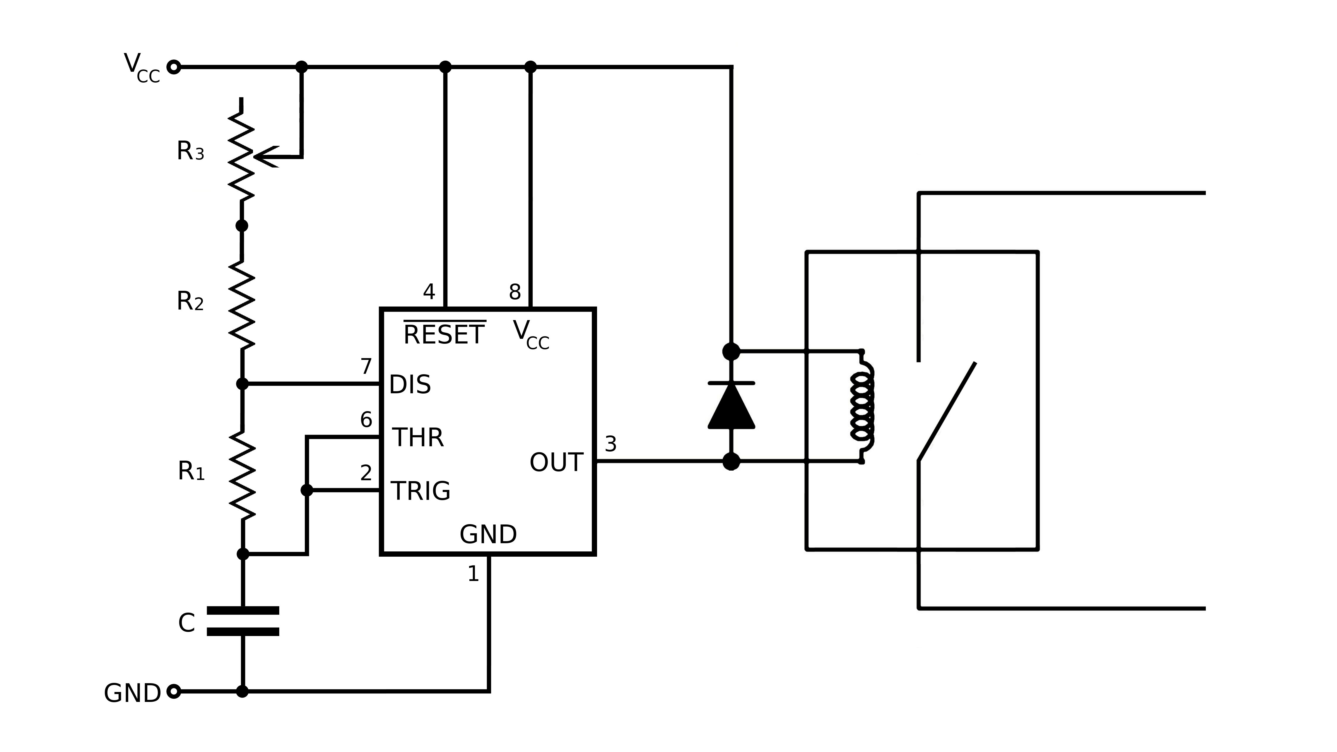
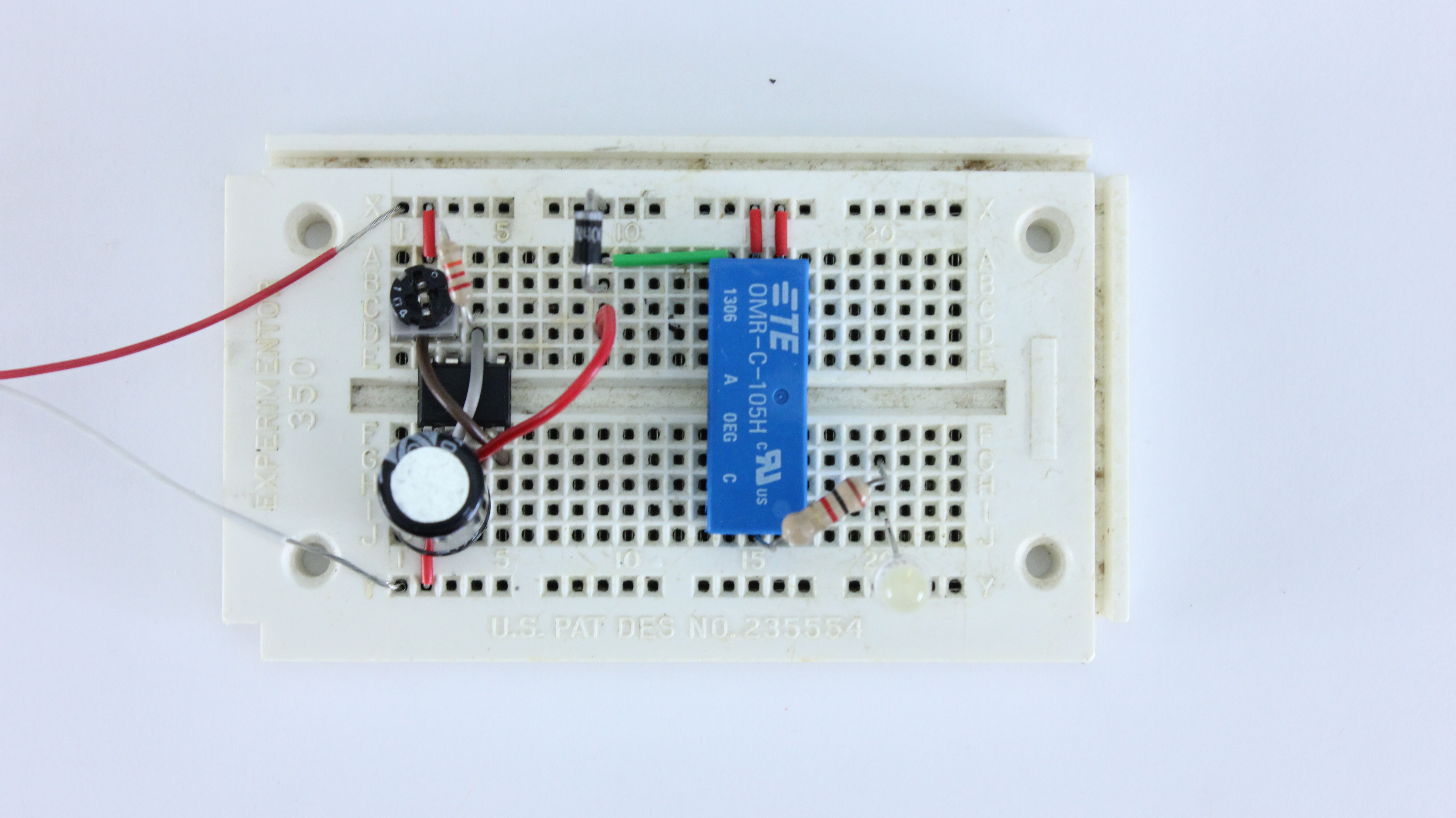
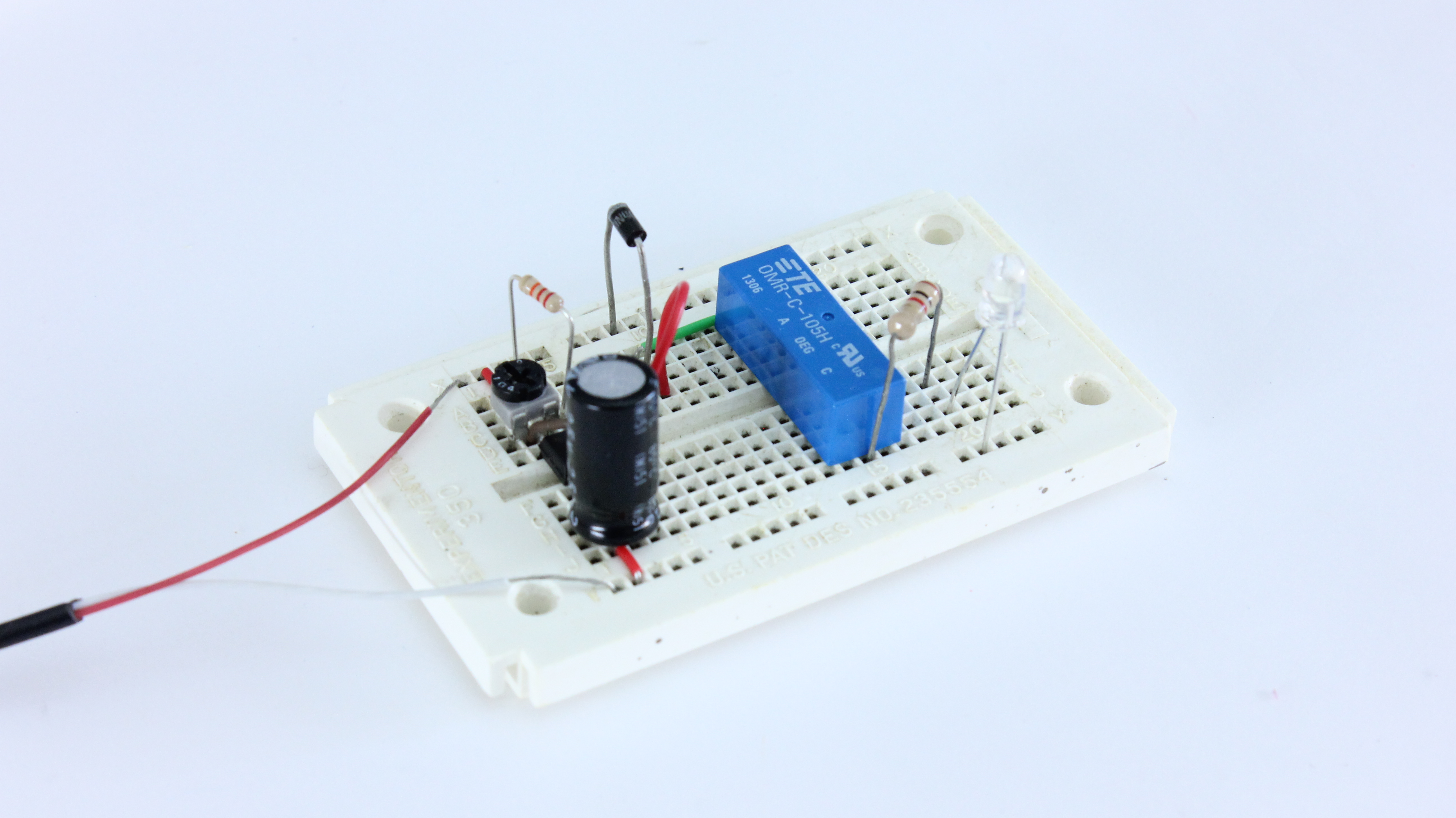
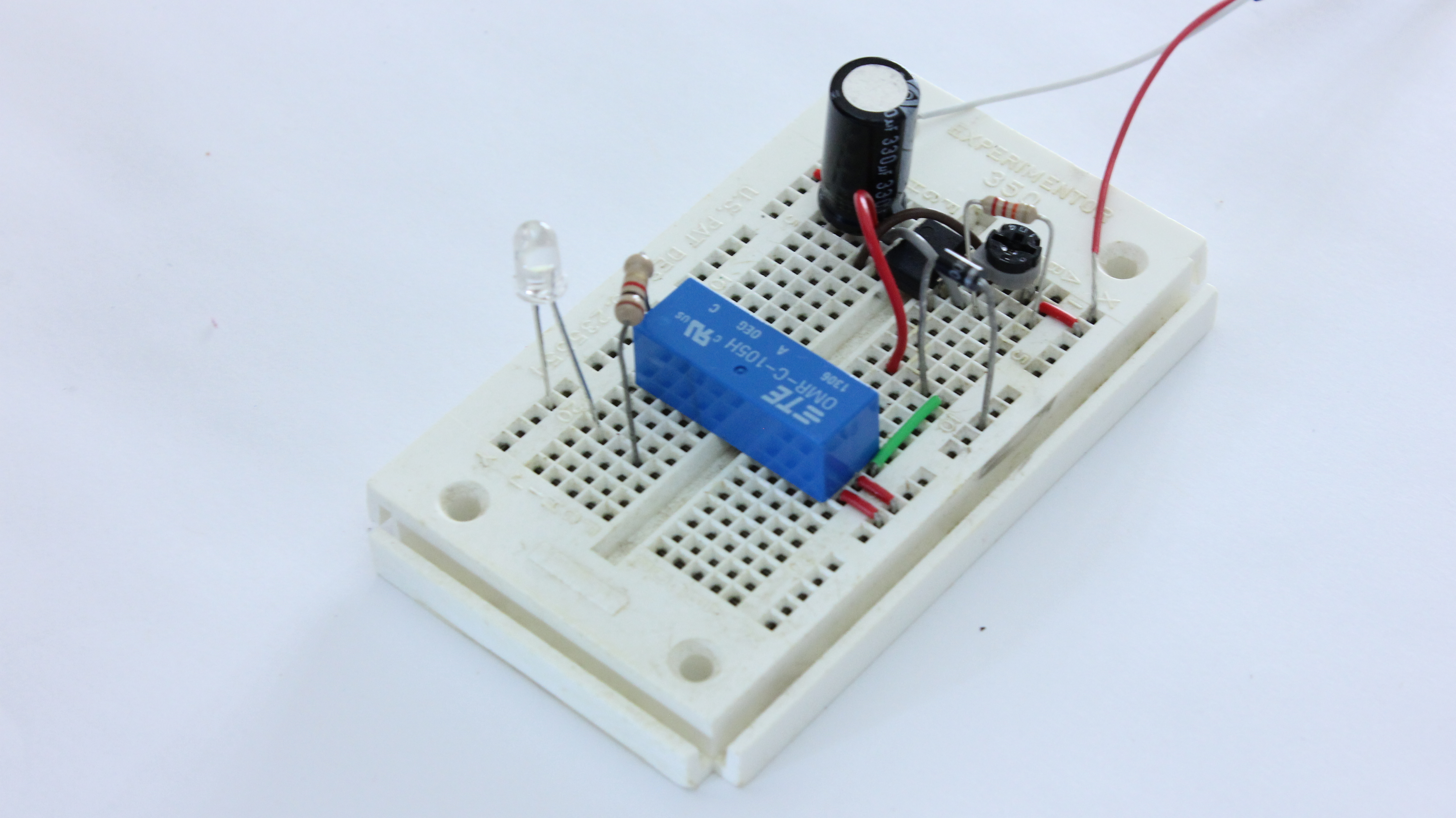
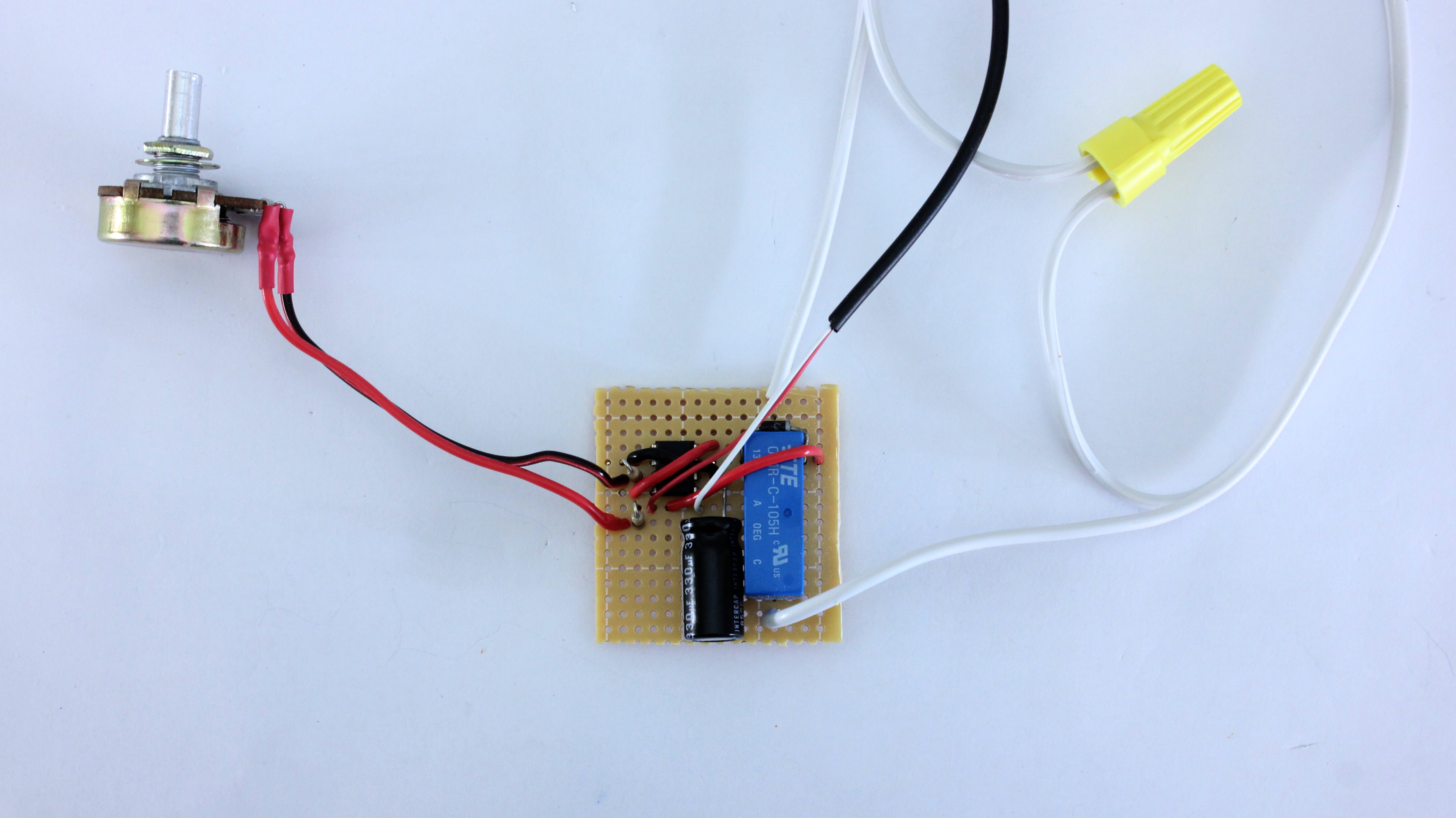
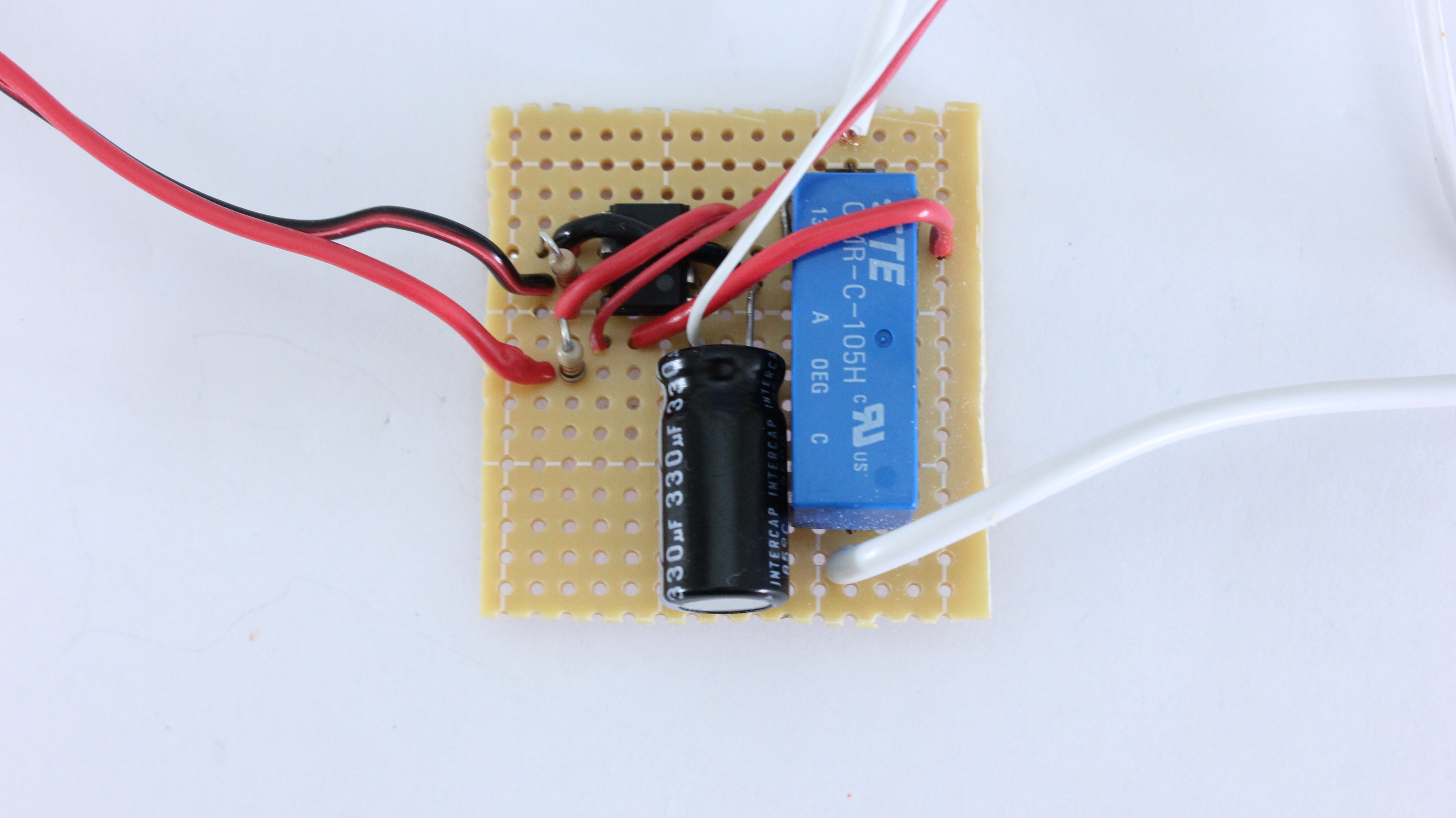
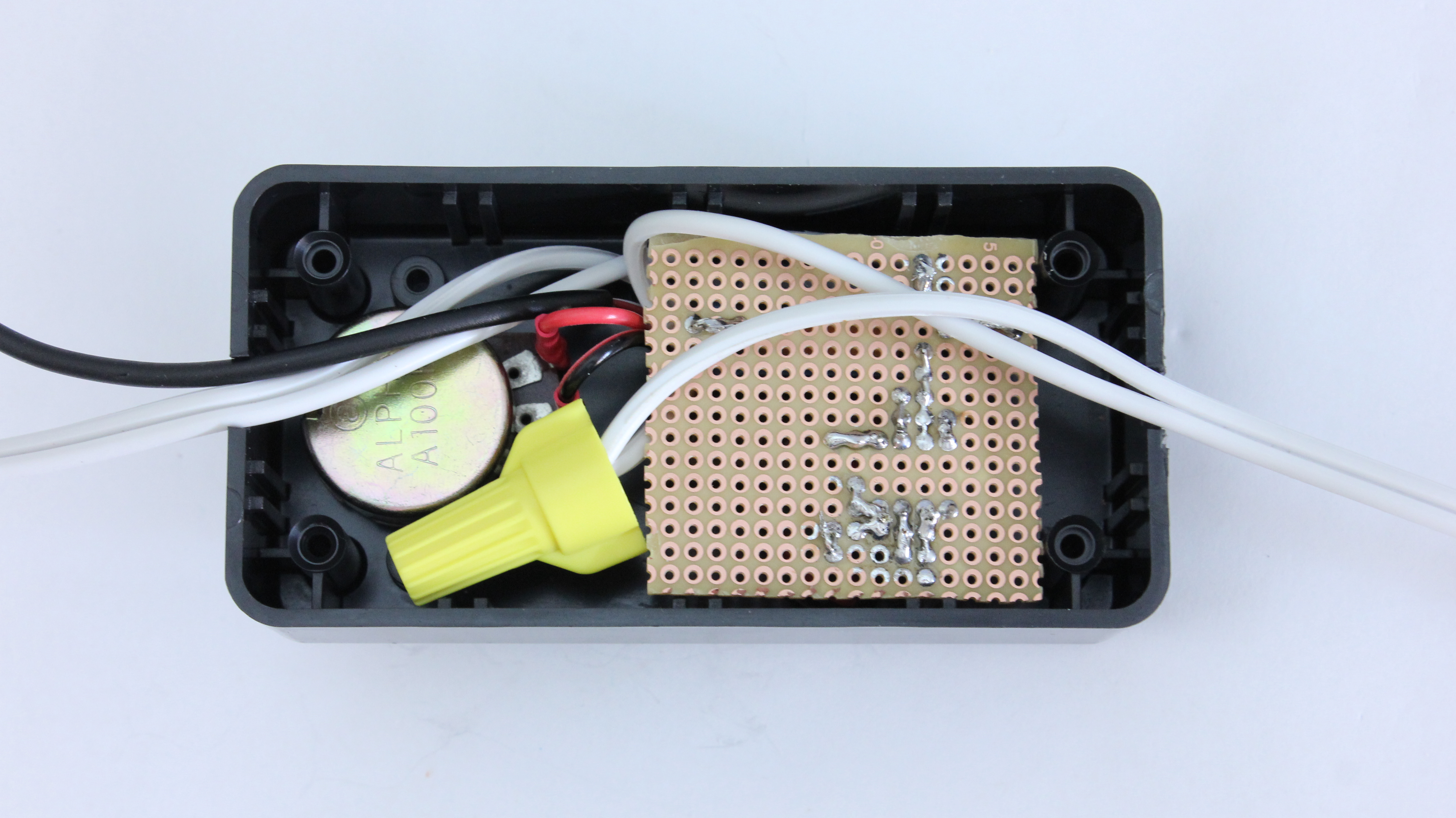
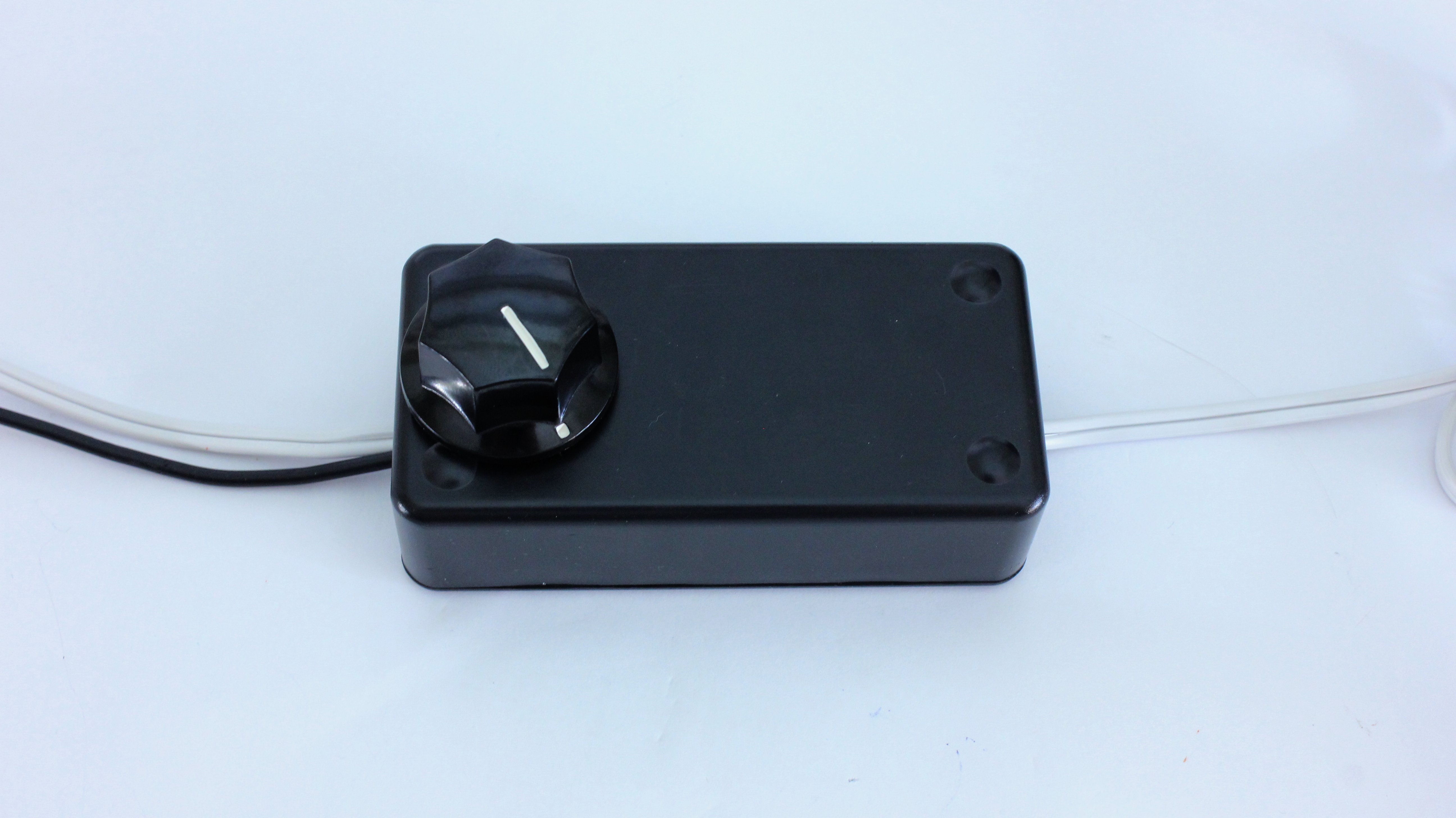
This is the control circuit that I designed for this project. It is based around a 555 timer IC. This configuration is known as “Astable Mode.” In this mode, the output of pin 3 is a series of HIGH and LOW pulses. This turns the relay off and on. The frequency and duration of these pulses is determined by the values of the resistors and the capacitor.
The time that the relay will be on is based on the formula:
t = 0.7 x R1 x C
The time that the relay will be off is based on the formula:
t = 0.7 x (R1 + R2 + R3) x C
In these formulas “t” is measured in seconds, “R” is measured in ohms and “C” is measured in Farads.
For my application, I used C = 0.000330F (or 330 micro farad), R1 = 22000 ohm (or 22 kohm), R2 = 000 ohm (or 1 kohm), and R3 = a 100000 ohm (or 100 kohm potentiometer). With these values the “ON” time was 5 seconds per cycle. Based on the setting of the potentiometer, the “OFF” time ranges between 5.3 seconds and 28.4 seconds.
You can change the timing of the on and off cycles by changing the values of the resistors and the capacitor. You can make the values whatever you want. But keep in mind that you always need to have at least 1 kohm of resistance between pin 7 and pin 8 on the IC chip. If you don’t, the IC can be damaged when the output turns on and off.


