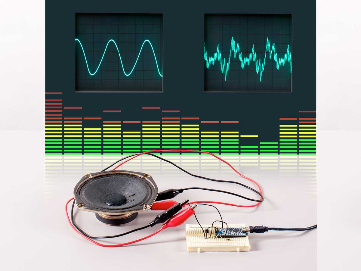
Listing 1 (download Listings 1–6 as a .zip file ) contains a sketch that uses a lookup table, fast PWM mode, and a 1-bit DAC to generate a sine wave.
LISTING 1
#include <avr/interrupt.h> // Use timer interrupt library

/******** Sine wave parameters ********/
#define PI2 6.283185 // 2*PI saves calculation later
#define AMP 127 // Scaling factor for sine wave
#define OFFSET 128 // Offset shifts wave to all >0 values

/******** Lookup table ********/
#define LENGTH 256 // Length of the wave lookup table
byte wave[LENGTH]; // Storage for waveform

void setup() {

/* Populate the waveform table with a sine wave */
for (int i=0; i<LENGTH; i++) { // Step across wave table
   float v = (AMP*sin((PI2/LENGTH)*i)); // Compute value
   wave[i] = int(v+OFFSET); // Store value as integer
 }

/****Set timer1 for 8-bit fast PWM output ****/
 pinMode(9, OUTPUT); // Make timer’s PWM pin an output
 TCCR1B = (1 << CS10); // Set prescaler to full 16MHz
 TCCR1A |= (1 << COM1A1); // Pin low when TCNT1=OCR1A
 TCCR1A |= (1 << WGM10); // Use 8-bit fast PWM mode
 TCCR1B |= (1 << WGM12);

/******** Set up timer2 to call ISR ********/
 TCCR2A = 0; // No options in control register A
 TCCR2B = (1 << CS21); // Set prescaler to divide by 8
 TIMSK2 = (1 << OCIE2A); // Call ISR when TCNT2 = OCRA2
 OCR2A = 32; // Set frequency of generated wave
 sei(); // Enable interrupts to generate waveform!
}

void loop() { // Nothing to do!
}

/******** Called every time TCNT2 = OCR2A ********/
ISR(TIMER2_COMPA_vect) { // Called when TCNT2 == OCR2A
 static byte index=0; // Points to each table entry
 OCR1AL = wave[index++]; // Update the PWM output
 asm(“NOP;NOP”); // Fine tuning
 TCNT2 = 6; // Timing to compensate for ISR run time
}
First we calculate the waveform and store it in an array as a series of bytes. These will be loaded directly into OCR1A at the appropriate time. We then start timer1 generating a fast PWM wave. Because timer1 is 16-bit by default, we also have to set it to 8-bit mode.
We use timer2 to regularly interrupt the CPU and call a special function to load OCR1A with the next value in the waveform. This function is called an interrupt service routine (ISR) , and is called by timer2 whenever TCNT2 becomes equal to OCR2A. The ISR itself is written just like any other function, except that it has no return type.
The Arduino Nano’s system clock runs at 16MHz, which will cause timer2 to call the ISR far too quickly. We must slow it down by engaging the “prescaler” hardware, which divides the frequency of system clock pulses before letting them increment TCNT2. We’ll set the prescaler to divide by 8, which makes TCNT2 update at 2MHz.
To control the frequency of the generated waveform, we simply set OCR2A. To calculate the frequency of the resulting wave, divide the rate at which TCNT2 is updated (2MHz) by the value of OCR2A, and divide the result by the length of the lookup table. Setting OCR2A to 128, for example, gives a frequency of:
which is roughly the B that’s 2 octaves below middle C. Here’s a table of values giving standard musical notes .
The ISR takes some time to run, for which we compensate by setting TCNT2 to 6, rather than 0, just before returning. To further tighten the timing, I’ve added the instruction asm(“NOP;NOP”), executing 2 “no operation” instructions using one clock cycle each.
Figure G Run the sketch and connect a resistor and capacitor (Figure G ). You should see a smooth sine wave on connecting an oscilloscope to Vout . If you want to hear the output through a small speaker, add a transistor to boost the signal (Figure H, below ).
Figure H 


