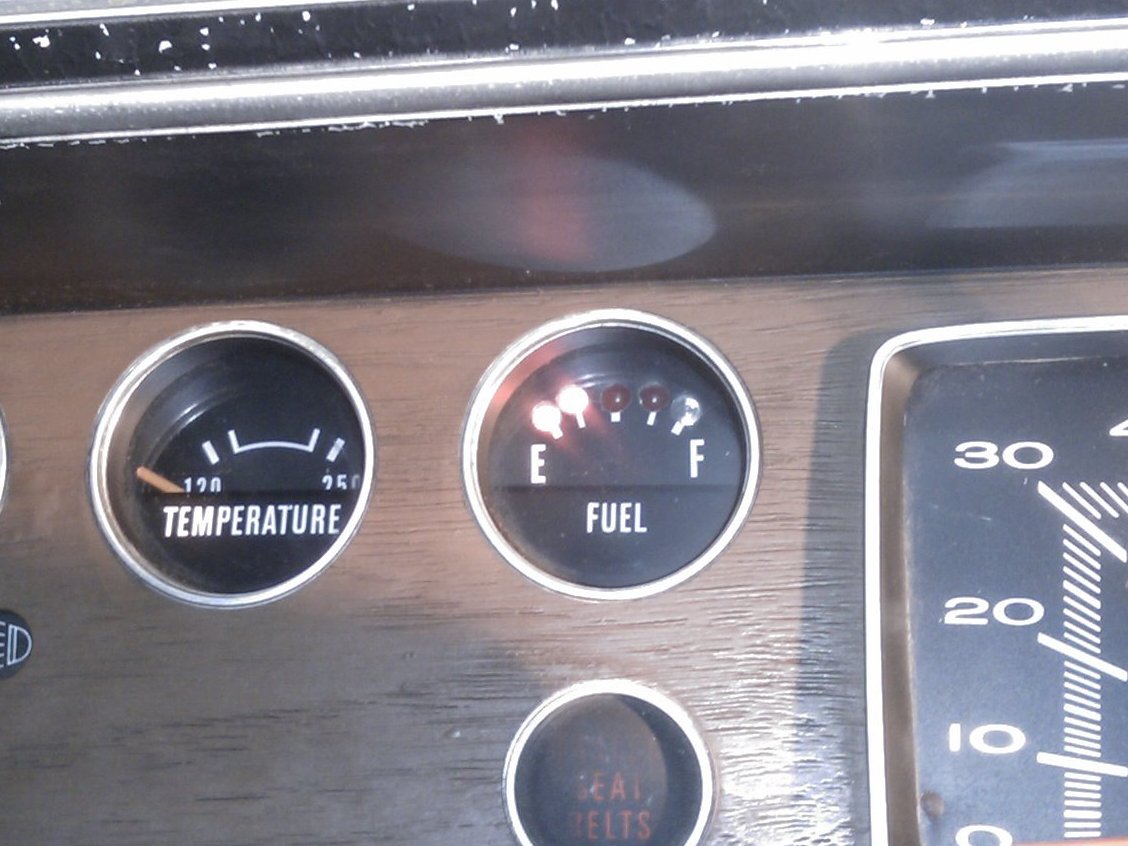
Arduino Fuel Gauge:

A few months ago, I hit a pot-hole while driving my 1974 Dodge Dart and my fuel gauge immediately went to “E.” For a split second I thought I lost all of my fuel! My father-in-law suggested I drive backwards over the pothole to fix the gauge. It didn’t work.

I researched some aftermarket options and I was generally unsatisfied with how they looked. Usually they were 3-digit 7-segment displays that read between 1-100 representing the percentage of fuel left in the tank. That style reminded me of the sad time in the early ’90s when car instruments were too digital.

I had one of them in an online shopping cart, ready to click “complete purchase” and sacrifice $50 and the analog soul of my car, when it hit me: “Hey, am I a maker, or not?” So I abandoned ship and decided to make a fuel gauge myself that would be cheaper and better than one purchased off the shelf.

Older vehicles usually have gauges that use a very simple analog circuit to read a resistance. You can read this resistance with an Arduino!

What will the next generation of Make: look like? We’re inviting you to shape the future by investing in Make:. By becoming an investor, you help decide what’s next. The future of Make: is in your hands. Learn More.

Project Steps

Make sure your gauges are analog! Most gauges from the digital age (’80s or newer) are processed by an onboard computer. (Tip: find the gauge wiring diagram in your manual. See photo of mine.)

Make sure your Sending Unit is working! Apparently most gauge problems are due to a faulty sending unit (basically a potentiometer attached to a float arm in your gas tank). Not in my case. An ohm reading while filling my gas tank revealed that the sending unit was working like a champ, reading 70 ohms empty and 10 ohms when full, which is exactly what the manual said it should read.

Remove your instrument panel. Consult your service manual or the Internet for the best way to do this for your vehicle specifically. This will save you time and effort because vehicles vary wildly when it comes to doing things like this.

Open your instrument panel. Instructions for this might not be in your manual. Just be careful and don’t lose any screws!

Remove and deconstruct gauge. Mine was held in place and electrically connected by two screw posts to a PCB. Once it is removed drill out the rivets and discard everything but the faceplate. Be careful not to damage the faceplate!

Drill the LED faceplate. Mark the holes for the LEDs and make sure they will be seen though the window in the reassembled instrument panel! When satisfied, tap your marks with an awl to keep the drill from traveling, and drill away. (Holes must be accurate, but perfection is not required. See photo. :)

Assemble the LED array – Method 1. Use hot glue to attach the LEDs to the back of the faceplate. I used 4 red LEDs and 1 blue.

Solder all of the LEDs’ ground leads together, then solder resistor legs to each of the LEDs’ positive leads. I used 100 ohm resistors for the red ones and a 220 ohm for the blue one because it was much brighter.

Solder the other legs of the resistors to wire leads long enough to reach where you are going to mount your Arduino. Do one more wire the same way for the ground leads of the LEDs.

Heat-shrink and/or tape all exposed leads.

Skip to step 6.

Assemble the LED array – Method 2. Method 1 ended up being a little too fragile for me; one of the LED leads broke off. This is the more rugged version. I included both methods to let the maker decide.

Use hot glue to attach the LEDs to the back of the faceplate. I used 4 red LEDs and 1 blue.

Place perfboard onto LED leads. I was out of perfboard so I etched this very simple board; perf would have been much easier. Also consider incorporating the resistors into this board, but make sure it will still fit into the instrument panel!

Solder LEDs, resistors and wires together as shown in the previous step. Remember, if you don’t put the resistors into this board (I forgot to) you still have to wire them in before they plug into the Arduino!

Use liberal amounts of hot glue to secure the board to the rear of the faceplate and to protect the connections.

Coding / Bench Test 1

Assemble the circuit on a breadboard as shown in the images. (Tip: use your LED faceplate as part of it, if completed.)

Wire in a potentiometer as a stand-in for your vehicle’s sending unit. Use one with a similar ohm rating (100 ohms in my case). Use only the middle pin and one of the outer pins.

Wire in a resistor between +5 and pin 0 that closely matches the rating of your potentiometer (again, 100 ohms for me).

Coding / Bench Test 2

Download the code here: http://bit.ly/vqEvq9 and load it onto your Arduino. If your car uses 70 Ohms for empty and 10 Ohms for full, you can skip the rest of this step!! :)

Set the potentiometer to the resistance of your sending unit is when the tank is FULL (10 ohms in my case).

Open the serial monitor on your computer with your Arduino still connected via USB. Write down the reading. (It will be a number between 1 and 1028.)

Set the potentiometer to the resistance your sending unit is when tank is EMPTY (70 ohms in my case). Write down this reading also.

Subtract the full reading from the empty reading. This is the range you will be working with. Now divide the range by the number of LEDs on your gauge. Figure out the numbers for each LED pinout as I did using the scratch paper. I had the circuit wired wrong when I did those calcs (oops) but I later corrected it using the numbers below. My Calculations: 106 full – 385 empty = range of 279 / no. of leds = 55 | 385 – 354 = LED1 | 353 – 292 = LED2 | 291 – 230 = LED3 | 229 – 168 = LED4 | 167 = 0 LED5

plug your numbers into the code where it looks like this: if ((analogValue>0) && (analogValue<354) ) { // digitalWrite(led1, HIGH); Load the code again.

Turn the knob on your potentiometer back and forth a few times and make sure the array of LEDs is sweeping on and off along with the change in resistance.

If it does you’re ready to install!

Wire in the Sending Unit

Find the wire to your fuel level sending unit using your manual. Verify with an ohm-meter.

Solder in the resistor and the wires that connect to +5 and pin 0 according to the schematic in step 6. Make sure these wires are long enough to reach where you are going to mount the Arduino!

Install your Arduino

Find a nice safe place for it and mount it with some double-sided tape.

Solder in a wire from an accessory circuit in your car (one that is only energized when the key is turned). Connect it to pin marked “V in” or “9v” on Arduino.

Solder in a wire from a good ground in your car. Connect it to pin marked “Gnd” right next to the pin mentioned above on the Arduino.

Connect the 2 wires you installed in step 9 to the pins “5v” and “Analog in 0”, respectively.

Connect the wires from the LED array to digital pins “2-6”, and “GND”. An easy way to remember which wire goes where is to hot-glue the positive leads into a makeshift plug while the Arduino is still on your workbench. (See photo.)

Real world testing.

Turn the key and your new gauge should be working!

Why not drive around like this for a while and be sure that the gauge is functioning properly before making it permanent?

That’s what I did, and it worked well, except when the car was running…. Huh? I don’t know why it was like that, but I did discover a fix. Install a second grounding method to the Arduino. (See next step, photo 3.)

Reassemble Instrument Panel.

Frame the gauge faceplate so you can see it clearly through the front window and attach it with… guess what. More hot glue!

Find a hole or drill your own in the back of the case to route the wires. I’m using an unused bulb socket.

Put the instrument panel back together.

Reinstall the Instrument panel into your car.

Find a more permanent home for the Arduino, and reconnect all wires to the correct pins.

Connect the metal part of the USB plug to ground. I used a screw and 2 nuts. (See 3rd photo.)

DONE.

*Whew*… This might need to be changed to “difficult,” but for now I don’t want to underestimate anyone. I think it was hard for me, though.

The code is very basic, just hacked together. I do hardware 1st and software 8th. If anyone feels like improving it I would be grateful. It does the job, though.

Also, I will eventually replace the Arduino with an etched board using the Atmega chip from this Arduino. Then this project will really be complete.

Fuel up! – go to the gas station BEFORE the far left LED is blinking.