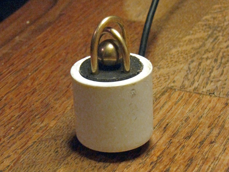
This clever mechanical switch remains open so long as it is balanced in an upright position. But disturb it in any way, and the ball falls against the bars of the cage and closes the circuit. Use it to control an alarm to protect your valuables, or to trigger a camera to photograph wildlife.

What will the next generation of Make: look like? We’re inviting you to shape the future by investing in Make:. By becoming an investor, you help decide what’s next. The future of Make: is in your hands. Learn More.

Project Steps

Drill out end of dowel

Print and cut out a copy of the supplied template. The circle should be 7/8″ in diameter.

If you can print on to an adhesive label, do that. Otherwise stick the template to a flat-cut end of your dowel with rubber cement.

Using a 3/32″ bit, drill the two gray-tinted holes at least 3/4″ deep, and the three other holes about 3/8″ deep.

Cut and finish base

Using a miter box, saw off the drilled-out end of the dowel 3/4″ from the end.

Only two of the five holes should penetrate all the way through the 3/4″ piece you just cut off.

Optionally, you may may stain or paint the base at this time. A black permanent marker worked well for me.

Prepare pipe cap

Choose a drill bit of the same diameter as your cable. Here it was 1/8″.

A quick poke with a hot soldering iron is a handy way to make a pilot dimple for your drill bit. Just eyeball it as close to the bottom of the cap as you can, allowing for the full diameter of the hole you’re going to drill.

Generally, melting, heating, or burning PVC is a bad idea. There’s probably no harm in a quarter-second’s poke with a soldering iron, but make sure you’ve got proper ventilation anyway, and don’t do it at all if you’re not aware of and comfortable with the risk.

Put the cap open-side down on the workbench and drill the hole.

Bend cage bars

Start with two pieces of 3/32″ brass rod, each about 4″ long.

The bending jig I used was just a handy bit of junk. Any 1/2″ diameter bolt or rod should work fine.

3/32″ brass rod bends easily with the hands. Bend it a bit too far, at first, then open the legs back up until they’re parallel.

Check the spacing of the legs against the holes in the dowel (those on opposite corners of the square).

If the legs are a bit too wide when parallel, give the bent end of the rod a gentle squeeze with a pair of pliers.

Cut cage bars to length

You’re going to make one long and one short “J.” 3/32″ brass rod can be cut with side-cutting pliers and a bit of elbow grease.

For the “long” J, cut one leg about 1 1/8″ long, measuring from the outside of the bent end of the wire.

Cut one leg of the “short” J about 7/8″ long, measuring the same way. This leg should be about 1/4″ shorter than the leg on the “long” J.

Don’t worry about the exact length of the longer leg on each J–they’re going to be trimmed to length later in the project.

Assemble cage

First, install the “short” J in the wooden base. Make sure its longer leg is lined up with one of the holes that goes all the way through the dowel, and push it in. Its shorter leg goes in the “blind” hole on the opposite corner. Go ahead and push it in until it stops.

Now insert the longer leg of the “long” J into the other “through” hole. Leave the shorter leg clear of its hole, for now.

Drop the brass ball into the pocket formed by the three legs that are already inserted in the base.

Rotate the short leg of the long J into position and press it home into the remaining blind hole. This action secures the ball in place; it should not be able to escape from the cage thus formed.

Now is a good time to test the action of your switch. Make sure that the ball can be set in a “neutral” position resting in the center hole that doesn’t contact any of the bars. Also make sure that the circuit closes across the two legs extending through the base when the ball falls against the cage.
Prepare cable

I wanted a round cable for the switch leads to match the round hole drilled in the pipe cap. I ended up using a piece of 1/8″ coax cut from an old RCA-style video cable.

Whatever style of cable you are using, it needs at least two conductors. Strip away the cable sheath with wire strippers or a hobby knife and expose the two wires. Strip their ends, as well, exposing bare copper.

Use a piece of scrap brass rod, or other 3/32″ stock, as a mandrel to twist a loop in the end of each wire. These loops will fit over the brass pins to form a strong mechanical connection before soldering.

Assemble connections

Using a small file turned on edge, cut a notch on each side of each brass pin extending from the switch base.

Notches should be about 1/8″ from the bottom of the dowel, and each cut about a third of the way through the thickness of the rod.

Slip the loops in the ends of the stripped wires over the two brass rods and snug them down in the notches you just cut.

Solder connections

As always when soldering, make sure your workspace has proper ventilation and be wary of burns. Do not allow flux to contact your eyes or skin.

Apply paste flux to each joint and heat with your soldering iron.

Touch the solder to the work and wait for it to melt and flow into the joint.

Leave the joints to cool, naturally, without disturbance, back to room temperature.

Insulate connections

Use heat-shrink tubing, if necessary, to make sure the two lead wires cannot accidentally short against one another no matter how the switch is turned.

If you’re using coaxial cable, like I did, a 3/8″ length of heat shrink tubing, slipped over the cable from the free end, works well to cover the uninsulated exterior conductor from the coax pair.

I like to use a cigarette lighter to shrink the tubing, but radiant heat from a soldering iron will work, too.

Trim pins to length

Use side-cutting pliers to trim the excess length of the brass pins just past the solder joints.

Once cut, each pin should extend about 3/16″ of an inch below the bottom of the dowel, and no more than 1/4″.

Final assembly

Thread the free end of the cable inside the PVC cap and out through the drilled hole.

Now is a good time to perform one more electrical test of the switch’s function. Once assembled, it will be very difficult to make any repairs.

Push the bottom of the dowel into the PVC pipe cap until the top of the dowel is flush with its rim. Rubbing the sides of the dowel with a bar of soap makes this a lot easier.

If your switch is too hard to balance in the upright open position, file a flat place on the bottom of the cap. You can “fine tune” the sensitivity of the switch by filing a bigger or smaller flat.

Conclusion

There are a number of variables that affect the mechanical sensitivity of the switch. The diameter of the detent hole drilled in the center of the dowel is an easy one to adjust; larger holes will tend to retain the ball longer and will decrease sensitivity. Likewise, the center of gravity of the switch assembly can be adjusted by how far the dowel is inserted, or by adding weight to its base. Using a PVC cap or a couple that's flat on the end, instead of rounded, will give a rather more stable switch. Experiment!