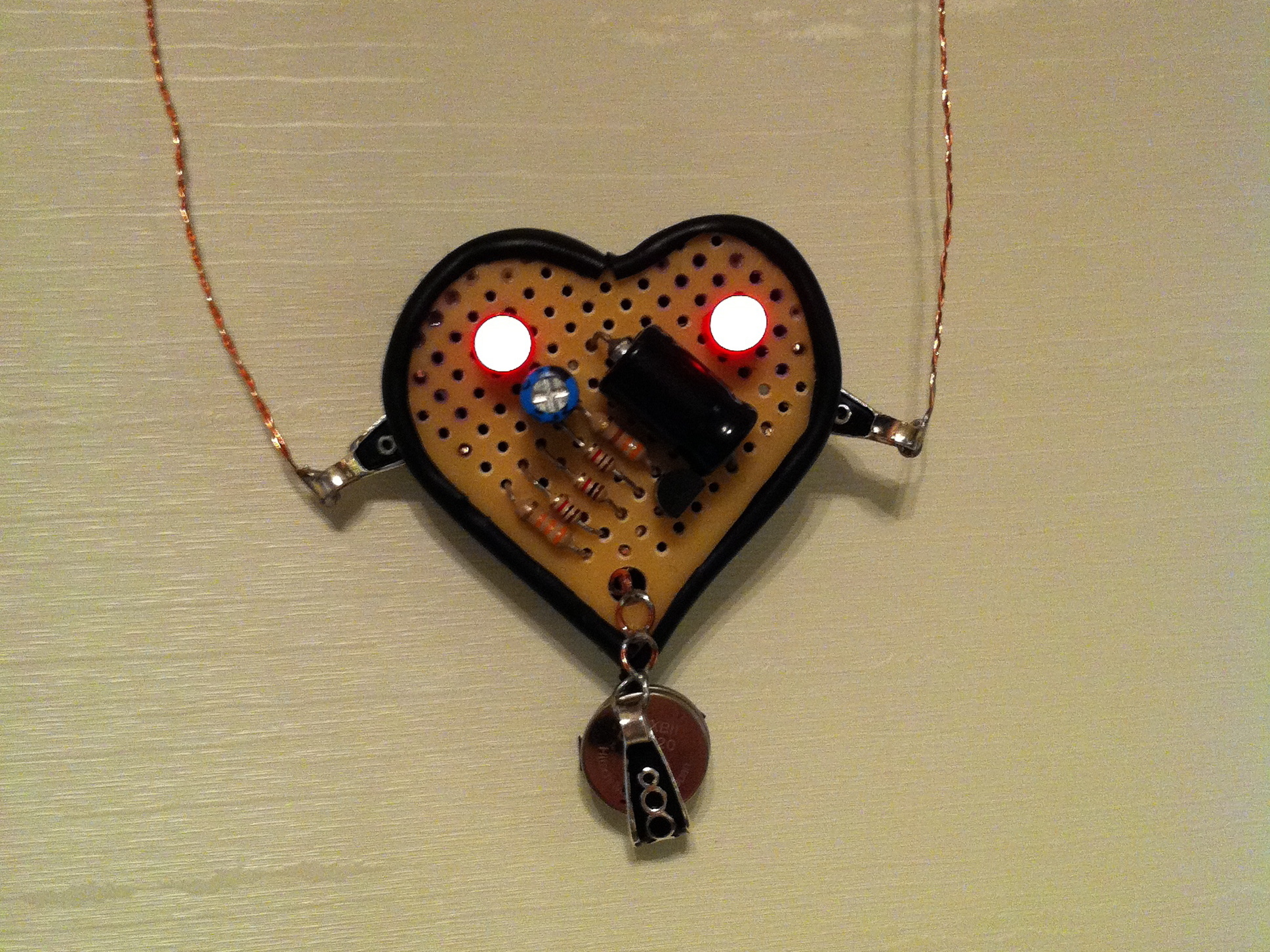
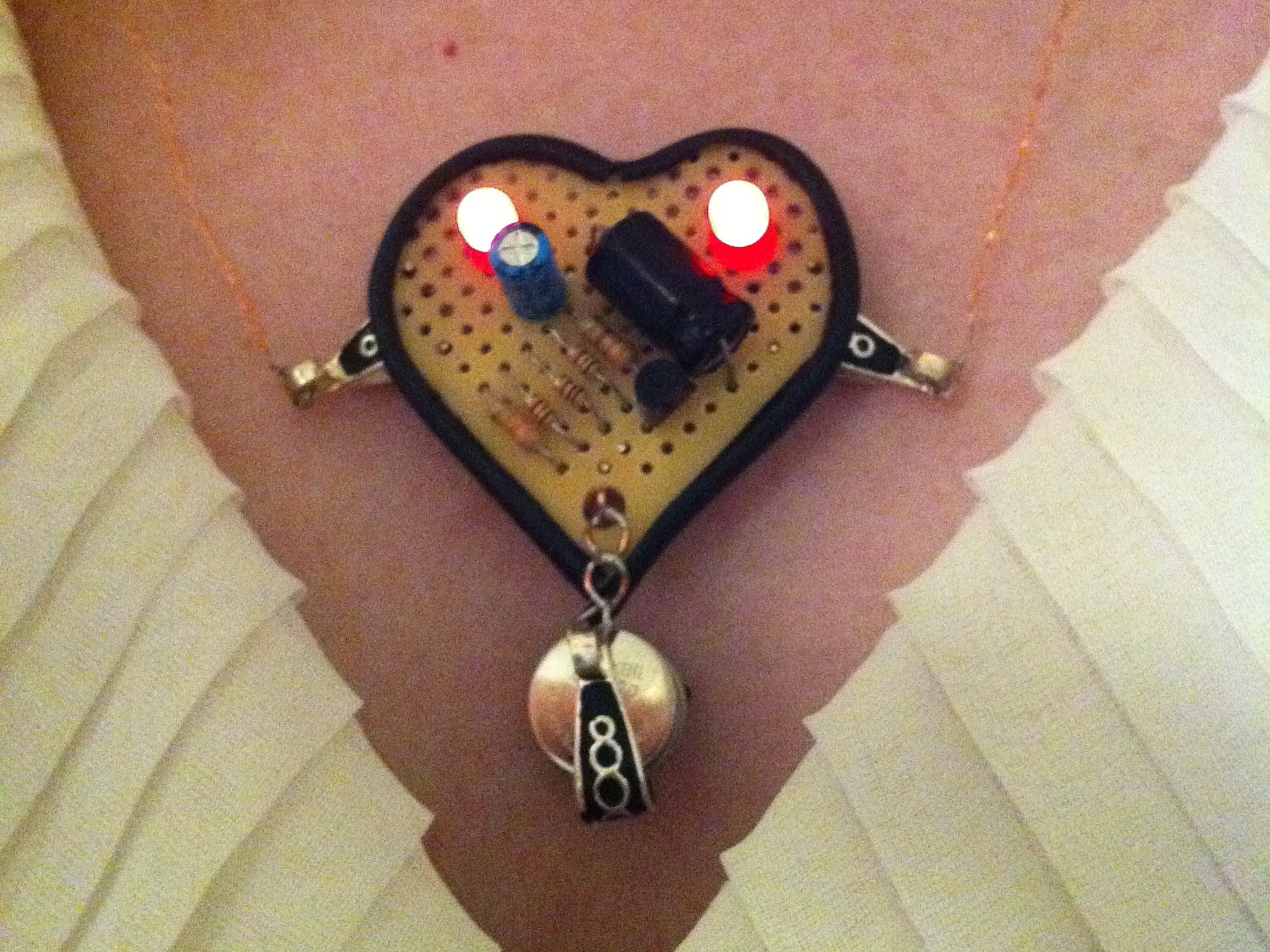
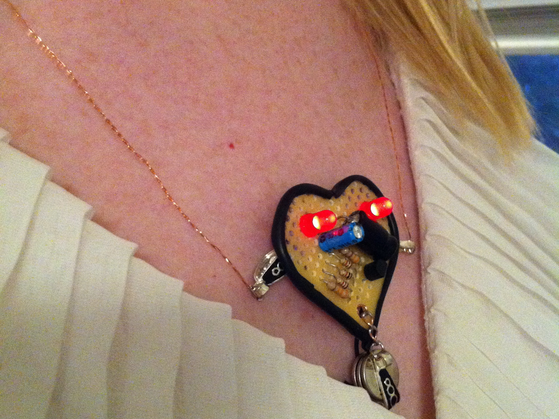
While reading through Charles Platt’s excellent book Make: Electronics, I came across this nice little circuit for making a gentle pulsing LED. I was struck by the “humanness” of the pulse, but couldn’t figure out what to do with it. Later I found a heart-shaped tag on some pants I had bought, and well, this is the result. I opted to use mainly scrap parts salvaged from old computers. I liked the hacky, recycled feel that gave it.

I took Charles’ circuit, and added a second LED for some symmetry. A bob under the pendant provides the power. The pendant’s chain is part of the circuit, so the clasp becomes the on-off switch.

What will the next generation of Make: look like? We’re inviting you to shape the future by investing in Make:. By becoming an investor, you help decide what’s next. The future of Make: is in your hands. Learn More.

Project Steps

Here’s the final pendant. Read on for all the gory details!

For more details, better pictures, and video of the pendant in action, visit: http://www.quinndunki.com/blondihacks/Bl…

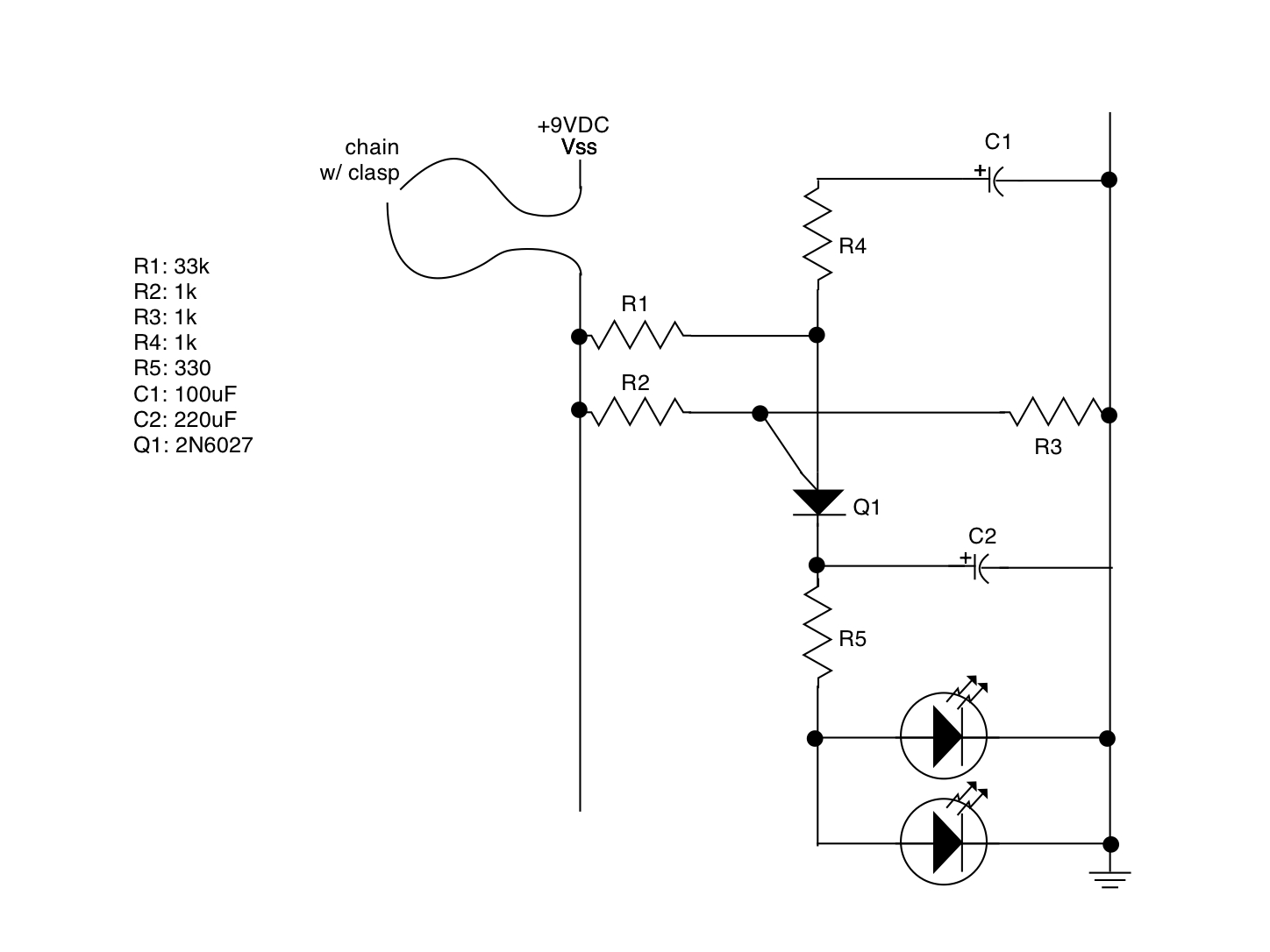
Here’s the schematic for the Beating Heart. This is taken straight from Charles Platt, with the addition of a second LED in parallel. The second LED raises the average draw of the circuit to about 4.5mA.

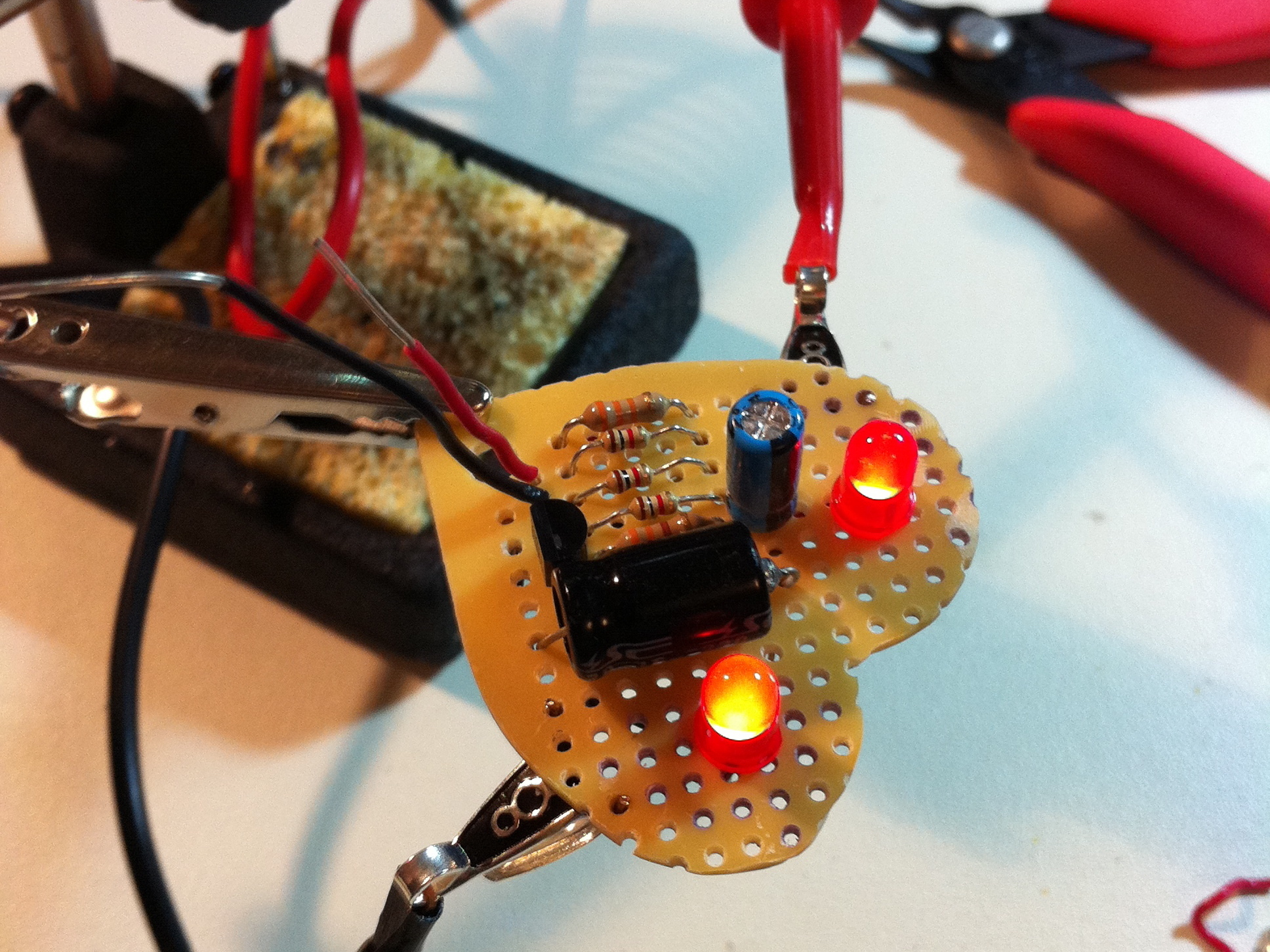
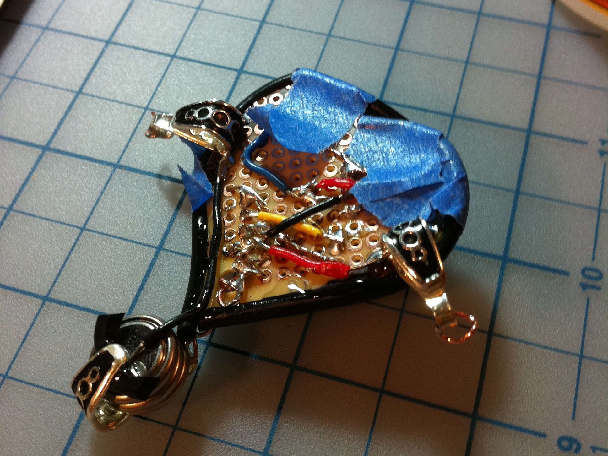
Once the circuit was built and tested, I used the aforementioned tag from my pants to trace the heart shape on the PCB, then cut it out with a Dremel. Where the schematic shows “chain w/ clasp”, I’ve soldered in these silver bails. You can find them in the Jewelry Findings section of craft stores. They are soldered to the PCB for structure, and soldered separately in to the circuit. Here I’m temporarily supplying power via the bails to make sure everything is okay.

Here’s the backside. I edged the PCB with some insulation that I carefully stripped off 16 gauge automotive wire and slit down one side. I’ve superglued the edging to the PCB.

The power supply is composed of another silver bail, shaped to hold three CR1220 button cells. The bail itself is Vss. The back is insulated with a scrap of superglued rubber, and a wire is glued to that to provide ground. The clip hangs under the pendant from a decorative copper chain (which also provides the positive electrical connection to the circuit).

Three CR1220s should power the pendant for about nine continuous hours.

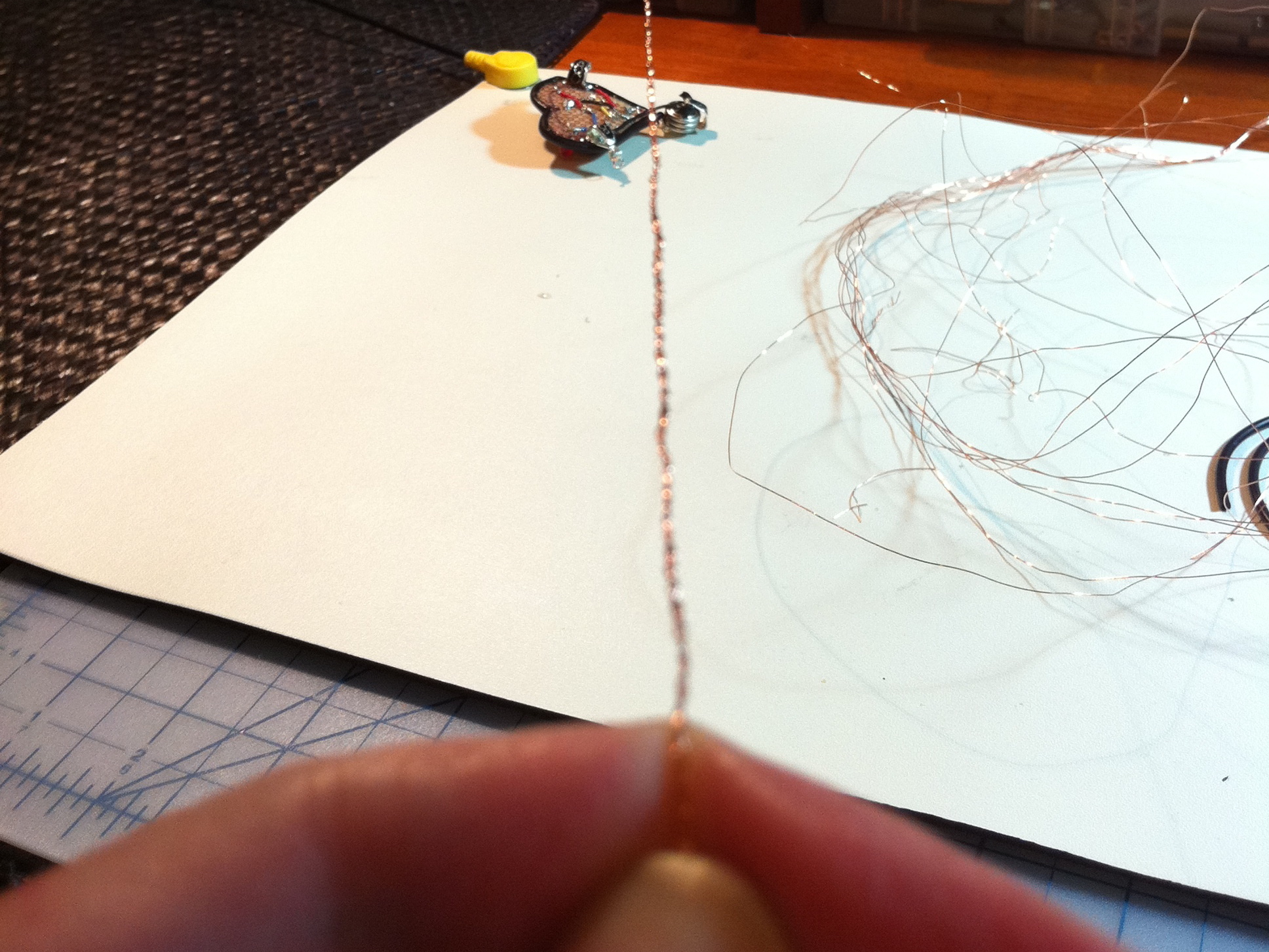
For the pendant’s chain, I needed something that would conduct. I tried several different kinds of jewelry chain, but couldn’t find any that conducted reliably when slack or in motion. I ended up making my own “chain” from scratch by unravelling some 16 gauge wire, and braiding together three strands. The braid is tight and consistent, so it looks pretty, and forms a solid connection in all conditions. This was just like making a friendship bracelet in juniour high school. Remember those?

The far end (not visible in this picture) is anchored to one post of my bench supply. That was a convenient way to hold it firmly so I could pull it tight during the braiding process. Copper wire is a lot more work to braid than thread, but I think the end result was worth it.

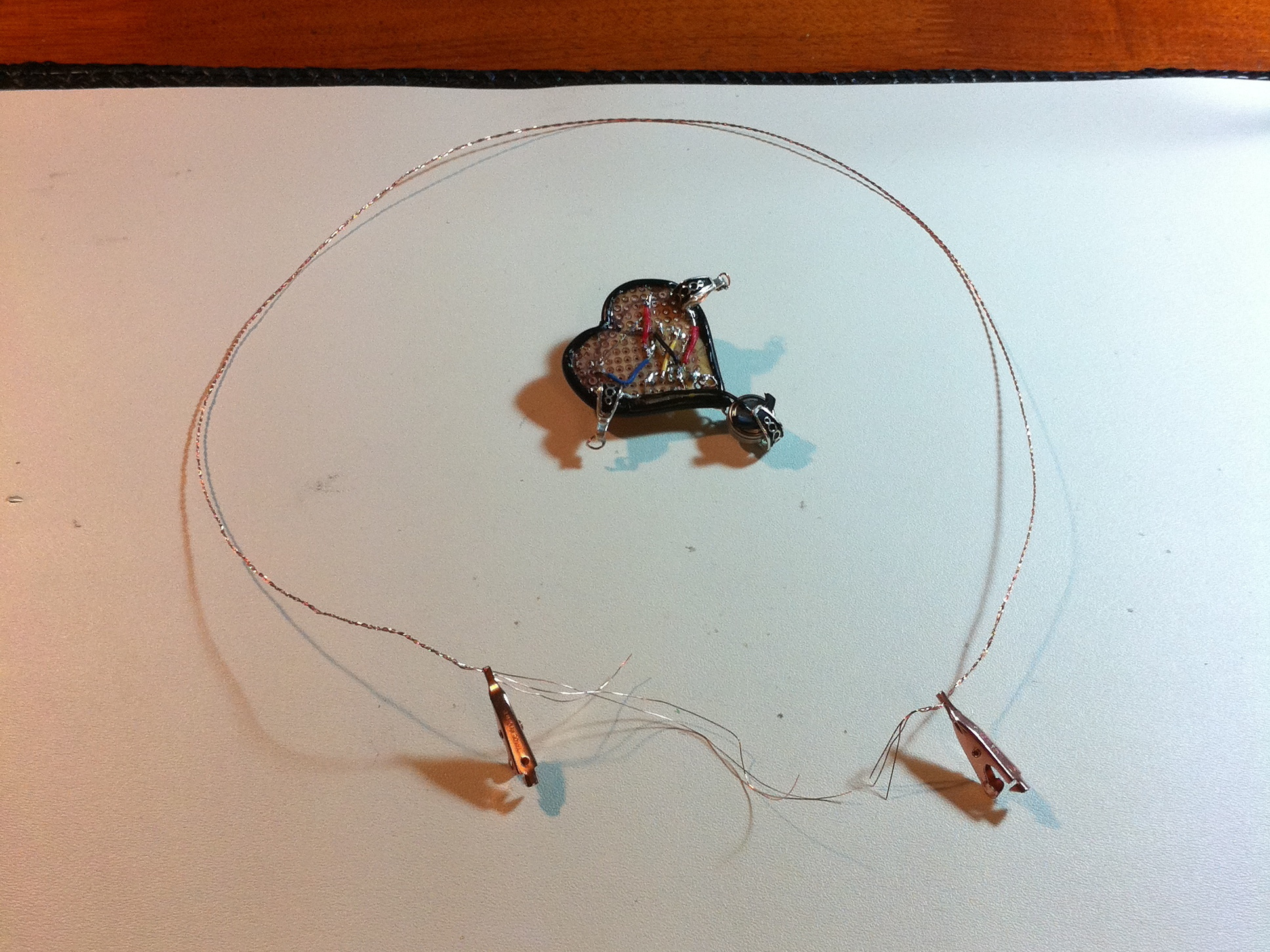
Here’s the final chain, ready to have clasps attached and ready to be fixed to the side bails.

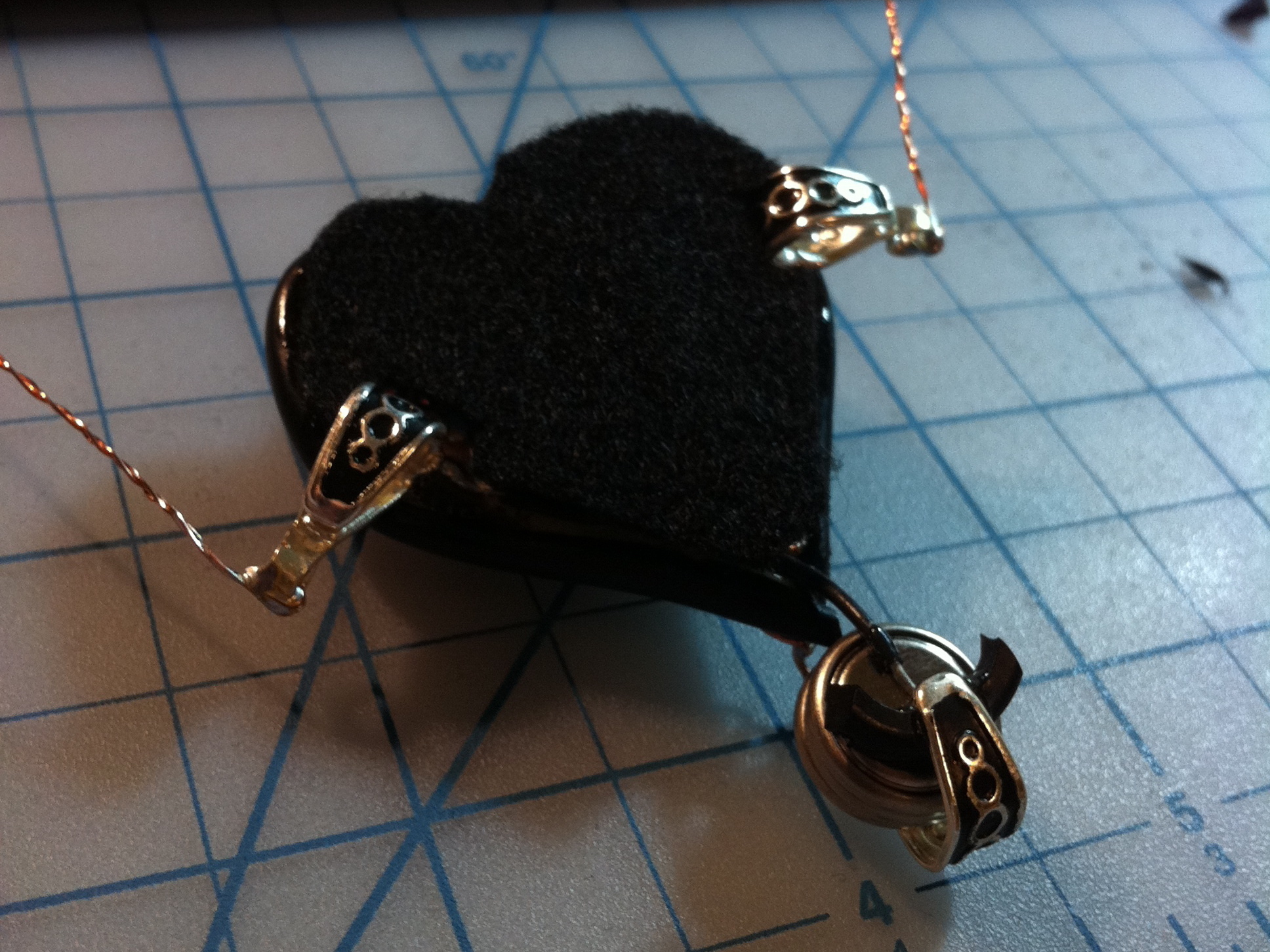
The back of the pendant is finished with a scrap of black felt. It looks clean, and keeps the prickly bits off your skin.

There you have it! I hope you’ll make your own, and have some fun with the design.

If you like this sort of stuff, visit http://www.quinndunki.com/blondihacks for more!