You will need the Rovera 2WD robot kit from the Maker Shed before proceeding.

What will the next generation of Make: look like? We’re inviting you to shape the future by investing in Make:. By becoming an investor, you help decide what’s next. The future of Make: is in your hands. Learn More.

Project Steps

Prepare for the Build

The book Make an Arduino-Controlled Robot, which is included in the kit, contains many helpful graphics and drawings during assembly. The best way to go about this assembly is to follow the steps here, but utilize the book in case you get confused or want to double-check something.

I will be referring to the book in certain spots, and will include specific page/figure references where I can. Please note that some steps of the assembly in the book will differ from this Make Project. This guide is the most recently updated, however, so use this when you have a choice!

First, solder together your Motor Shield and mount it on your Arduino Leonardo. Instructions for assembling the Motor Shield can be found here.

Modify the Motor Shield

In order to easily plug the sensors into the Motor Shield, let’s add a few headers.

First, grab a single row of female headers, and insert it into the board as shown. It should be six pins long.

Bend the leads with pliers or tape them in place so they don’t fall out the board while you’re trying to solder.

Tip: Solder just one lead to start – check your work and realign the headers if they’re off before finishing the row. I introduce a cool technique for dealing with this in Step 13, if you want to briefly skip there…

Modify the Motor Shield MORE

Repeat the same process, but with the 2×6 set of female headers. Once again, solder just one pin to start, to make sure everything’s aligned correctly.

Grab the 1×6 row of male headers and break it in half, by holding the row with pliers while you put pressure on one end. We’ll be plugging the servo motors into these two 1×3 rows of male headers.

Solder these just like you did the other headers.

Preparing the Ping Sensor Mount

The first subassembly we’re going to put together is the Ping Sensor mount. All required parts can be found with the sensor itself in a small plastic bag. Open it up and take all the parts out now.

The first step is to enlarge two of the holes in the servo horn, so we can fasten it to the aluminum sensor mount. Remove the horn from the servo with a small Phillips-head screwdriver. Drill through the second hole on two of the horn arms with a 3/32″ bit, as seen in the photo.

If you don’t have a 3/32″ drill bit, you can also use a knife to enlarge the hole.

Now insert the circular rubber piece into the hole of the aluminum sensor mount. This will protect the sensor cable from harm.

Mounting the Ping Sensor

Now grab the two smallest screws and matching nuts from the pile of parts and fasten the servo horn to the aluminum sensor mount.

Make sure the circular protrusion from the horn faces away from the mount, so you can attach it to the servo motor again.

Once the horn and mount are attached, put the assembly back on the servo and replace the black screw to hold everything in place.

The servo doesn’t have continuous rotation capabilities, so it’s likely that the mount isn’t properly centered. Wiggle the mount back and forth and adjust the position of the horn on the servo to make sure the mount faces forward when the servo is rotated half-way around.

Next, grab the Parallax Ping sensor and mount it to the aluminum sensor mount with two nuts, bolts, and plastic spacers. Then grab the cable and plug it into the sensor, ensuring that the black wire lines up with the Ground pin on the sensor.

Mounting the Motors

Time to build the chassis! We’ll start by fastening the two motors to the main frame.

Each motor is attached to the frame with M2.5 hardware, included in the small hardware bag. Use a 25mm M2.5 bolt through the frame and motor, with a washer, lock washer, and M2.5 nut on the other side.

Repeat this once more for the first motor so it’s secured in place by two sets of hardware, and then repeat the whole process for the second motor.

The normal washers are flat, but the lock washers are bent to create tension between the hardware, preventing them from coming loose due to vibration.

Don’t forget to attach the wheels! They fit right onto the motor shafts, but only at a certain orientation.

Mount the Caster, Sensor Mount, and Battery Holder

The caster wheel is next. Without this, the robot will have trouble turning. You’ll need two M4 bolts, two M4 nuts, and the caster itself. The M4 hardware is the largest in the bag.

Once the caster is in place, we can add the sensor bracket. This part will act as a mounting point for the line-following and edge-detecting sensors. Fasten it to the underside of the main frame, or it will get in the way of the battery holder. Do this with two of the bolts in the bag that have flange heads.

The battery holder is fastened directly to the main frame with the only two countersunk bolts in the hardware bag. In order to make your life easier later on, make sure the red and black wires are facing the back of the bot.

Soldering the Motor Leads

It’s finally time to solder! Start heating up your iron and grab a pair of wire snippers and strippers while you wait.

Cut two pieces of red/black wire, each around 7.5″ long. Spread the black and red wires apart partially and strip 1/4″ off each wire, at both ends.

Bend the legs of the two 0.1 uF caps until they fit in the two motor terminals. Insert one into each set of terminals, along with one length of the red/black wire, with the red on the bottom.

In this case, the capacitors suppress electrical spikes generated by the motor, preventing major interference with the Arduino and resulting in smoother operation.

To make it easier to plug the motors into the terminals on the Motor Shield, tin the other end of each wire, as in the second photo.

Preparing the Top Plate

Now grab the top plate of the bot and the red power switch. First, thread one of the thin & wide M6 nuts onto the shaft of the switch. Then, slide the star-shaped lock washer on top, and insert the switch into the top plate. Now add the second M6 nut and tighten it all together!

We’ll accomplish a similar task with the charging jack, only with one less nut. Refer to Figure 3-13 on page 30 of Make an Arduino-Controlled Robot for details.

Soldering the Power Circuit

Now you have a choice. If you’d like to eventually trickle-charge your robot, solder up the circuit according to the first photo. If you wouldn’t like to trickle-charge in the future, solder up the simpler power circuit, shown in the third photo.

I chose the trickle-charging circuit. The second photo shows the setup – take care not to short anything out on the metal frame or another component.

If you have any heatshrink tubing lying around, use it here. If you don’t have any, no worries – just make sure nothing’s getting shorted on the frame.

Attach the Top Plate

Grab that round, flat top plate and place it onto the main frame, with the large rectangular cutout (which the Ping servo will fit into) up front.

Screw four flange head bolts into the bottom frame. You may have to nudge the main frame’s side walls into the right position before screwing the bolts in.

Now decide how you’d like to mount the Arduino to the frame. If you want the board to be easily removable, stick the loop (or “hairy”) side of the hook-and-loop onto the Leonardo, and the hook (or “pointy”) side onto the top plate.

If you’d like to mount your Arduino more securely, you can use the brass standoffs and nuts, through the three mounting holes of the microcontroller.

Plug In the Electronics

Mount the Arduino and Motor Shield stack onto the top plate in the orientation shown in the first photo.

Plug the motors and power source into the board as shown in the second photo.

It’s helpful to tin all wires before plugging them into the motor terminals.

Next, plug five AA batteries into the battery holder and flick the power switch. The little green LED on top of the Motor Shield should turn on.

If the LED doesn’t turn on, head back to Step 8 and make sure you wired up the power circuit correctly.

Prepare the IR Sensors

Now it’s time to solder male header pins to the IR sensors, for line following and edge detection. You should have three sensors and a row of three male headers for each.

Place the short side of the headers into the PCB and set both on a flat surface, as seen in the first photo. Now solder just one of the pins.

At this point, the headers are probably at a weird angle. The second photo shows a neat way to fix this – hold the sensor and headers upside down while re-heating that joint you just soldered. Once the solder liquefies, gravity should take over and the headers will automatically seat themselves perpendicular to the board. Cool, right?

If you don’t have a pair of helping hands, you can hold the sensor while you do this. Just be careful not to burn yourself.

Now you can solder the last two pins with ease! Repeat this whole step two more times to finish all three sensors. (You only need two sensors for edge detection, but you need three for line following!).

Mount the IR Sensors for Edge Detection

If you’d like to do edge detection, mount the sensors as seen in the first photo, with two of the smallest nuts, bolts, and spacers you can find in the hardware bag.

If you’d like to skip edge detection and go straight to line following, head to the next Step.

Don’t worry, you can always come back to edge detection later on!

Next, find your 6-wire ribbon cable, and split it right down the middle.

Split and tin each of the three wires, and solder them to a 3-pin female header. Once the soldering’s done, you can plug the female header right into the sensor and the other ends of the cable into the motor shield. Refer to the second image for a helpful wiring diagram.
Prepare the Bot for Line Following

Ok, take the brown perfboard out of its bag and use a pen to mark three lines where the three IR sensors will be mounted.

Ideally, there should be four holes between each pen mark and the next.

Drill two holes as shown. I used a 5/32″ bit, but anything large enough for the flange bolts in the hardware bag will do just fine.

Start Soldering the Line Following Circuit

Start with the black (GND) and red (PWR) wires. Refer to the first image for a layout of where they should be.

I didn’t have the holes drilled into the board at this point, but you should drill yours before going any further if you haven’t already.

Don’t forget to solder the female headers in place as well, to hold the three IR sensors. These should all be facing down, and perpendicular to the perfboard when everything’s said and done.

Prepare and Solder the Ribbon Cable

Next, grab the nine-way ribbon cable. Split it up into two sections – one of 5 wires, and another of 4. To easily line everything up later on, the cable with 5 wires should have the red wire on one end. You can set the 4-wire strand aside as backup.

Now split the five wires up and strip about 1/4″ off each. Orient them on the perfboard as shown in the second image, and solder.

Looking from left to right, you should have one wire connected to each of the rightmost pins of the female headers. The last two wires of the ribbon cable should be soldered to the first and second pins of the rightmost female header. Did you get all that? Check out the final image – it will be helpful.

Attach the Line-Following Subassembly to the Bot

Now use two flange bolts and nuts to fasten the perfboard to the sensor mount on your bot. You may need to loosen the battery holder in order to squeeze the perfboard underneath it.

Now wire everything up on the motor shield. Refer to the second and third images for a diagram of the shield pins. You should see the 0-5 terminals labeled on the Motor Shield itself.

Attach the Ping Sensor Mount

To attach the Ping sensor assembly, slide it right into the rectangular slot on the front of the frame. Use four nuts and bolts to fasten it in place!

Now it’s time to plug in the two servos. Refer to the first image to make sure you’re doing it correctly.

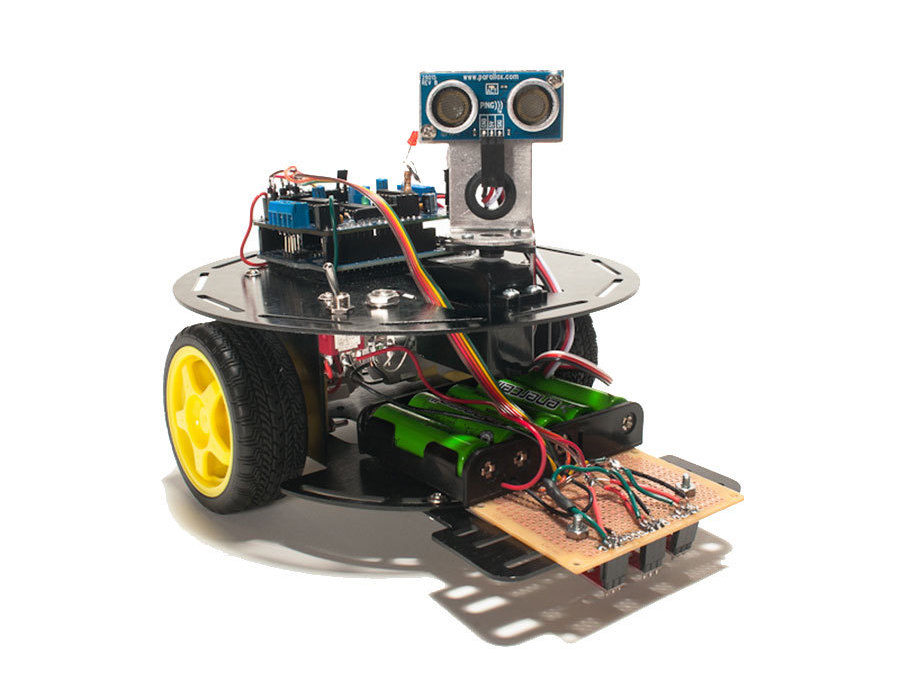
You’re done with the build! There are a few additions you can still make to the bot, and I’ll go over those in the next step. Head to Chapter 5 of the book (page 71) to start playing with Arduino code.

Additional Robot Advancements

For remote control, refer to Chapter 11 (page 185 of the book). You can plug the IR sensor right into the motor shield, as seen in the first image. You’ll also need a standard TV remote.

You can also monitor the battery voltage of the bot through the code. For wiring this up, you’ll need two resistors – refer to Appendix D (page 221) and the second photo for more information.

And that’s it! If you have any suggestions on how to improve this tutorial, or questions about the kit, please leave a comment below.