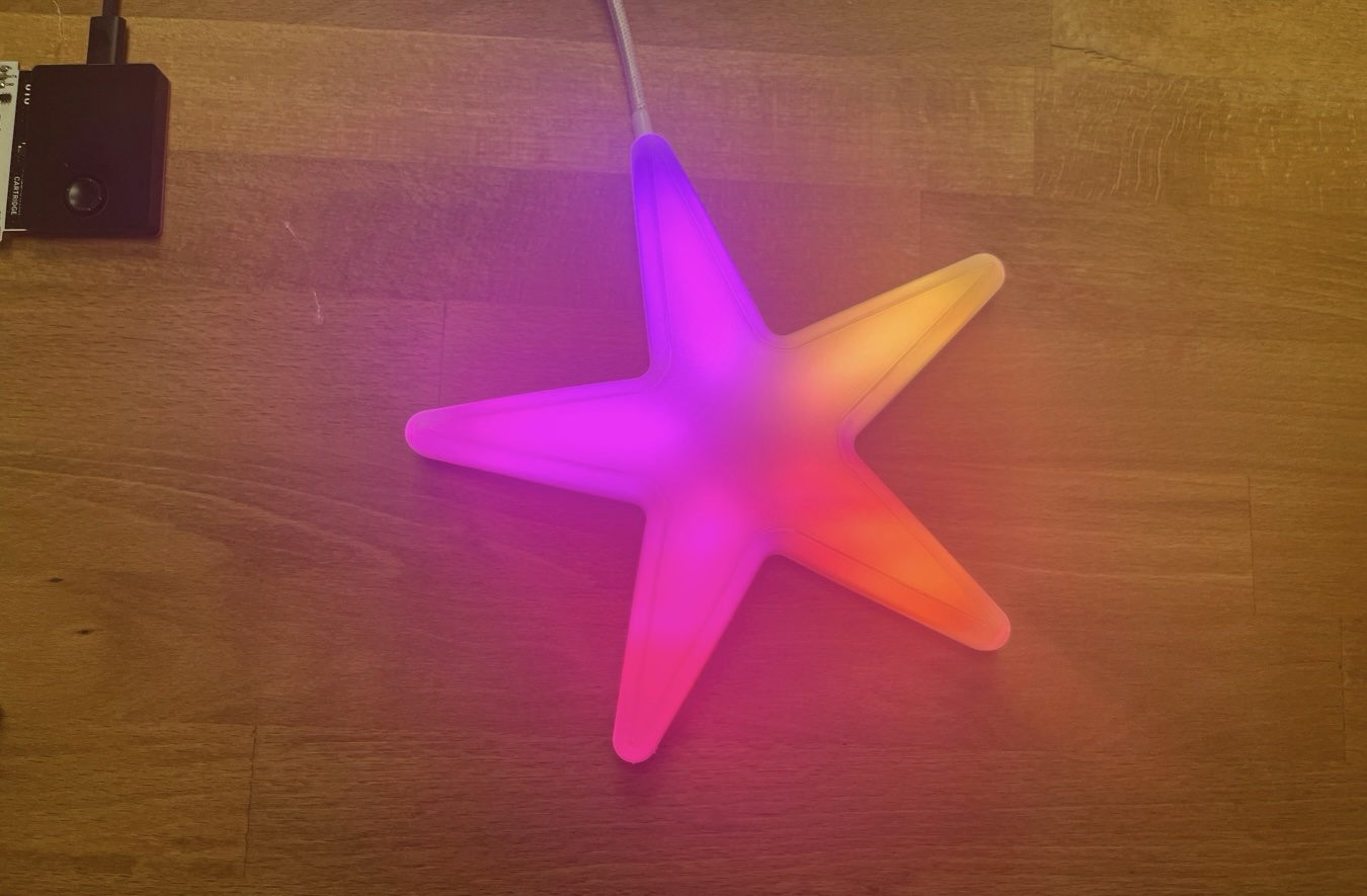
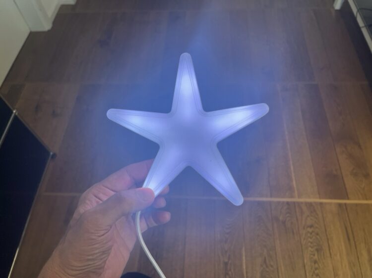
A glowing LED star is not only a real eye-catcher, but also an exciting craft project that combines 3D printing, soldering, and programming. In these instructions, we will show you how to make an atmospheric LED holiday star from just a few parts in a few hours that will make your home shine in festive splendor.

As a maker, you’re always under a bit of pressure to justify yourself to the family when you retreat to the craft room on the weekend. This time it’s different, because we’re creating something great in a short space of time that will delight young and old alike. Maybe we’ll even win over this year’s Christmas tree decorating team and our chic craft will be allowed to decorate the top of the tree this year.

Our star contains 25 individually addressable RGB LEDs. When constructing the housing, we made sure that the individual light points are not visible as such. When all the LEDs are switched on, the star is illuminated homogeneously with a diffused light. This way you can achieve interesting effects through clever programming, for which you would normally need many more pixels and a higher resolution.

To keep the soldering effort to a minimum, we use an already connected LED matrix, from which we break out strips, position them in a star shape, and solder them together again.

The Pixelmatrix cartridge provides us with five pre-wired LED pixel strips.

The housing is created using a standard 3D printer and consists of just four parts, which are either glued together or fastened with four M3 screws. The cover serves as a diffuser. It deflects the light from the individual pixels so that they’re not individually visible.

3D design of the star with screwed housing and optional adapter.

The effects are programmed in NanoPy, a programming language optimized for microcontrollers and that is strongly oriented toward Python.

What will the next generation of Make: look like? We’re inviting you to shape the future by investing in Make:. By becoming an investor, you help decide what’s next. The future of Make: is in your hands. Learn More.

Project Steps

Plug-and-play parts

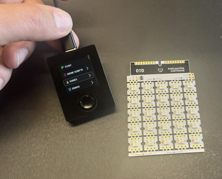
A microcontroller is needed to control individually addressable LEDs. There are countless of them. The Oxocard Connect, which is supplied with a ready-made small operating system, is an easy way to get started. Various expansion boards can be plugged in via the built-in cartridge slot and used immediately. In our example, we’re using the Pixelmatrix cartridge, which consists of 25 pixels. If you plug it in, an animation is already displayed without having to install or program anything. This is an ideal basis for our small project.

This pixel matrix has the advantage that we already have five hard-wired LED strips on the board, which are already connected to each other. We only have to break them out and rewire them. This only requires 12 short wires to connect GND, VDD, and the signal pin of the five strips. As we use all 25 pixels of the original matrix again, we can even use the existing firmware of the cartridge for initial tests and don’t have to program anything.

The Oxocard Connect with the Pixelmatrix cartridge.

Print the housing

The star consists of four plastic parts. We recommend printing the parts in white so that the luminosity is not reduced. PLA or PETG is a suitable material. PLA has a lower melting point, so PETG is preferable.
All parts are available in STL form below.

The top, back, and PCB holder are printed directly on the printing plate without raft and support structures. The adapter part is the only one printed with support structures.

We tested the parts with a layer height of 0.2mm on a Prusa MK4 and a Prusa XL using white PLA.

Solder the LED wires

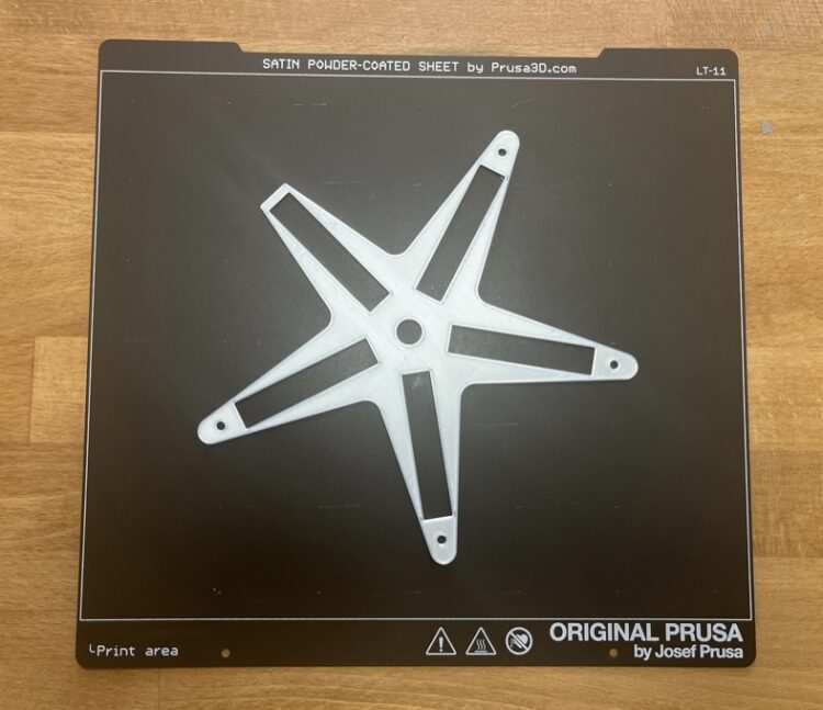
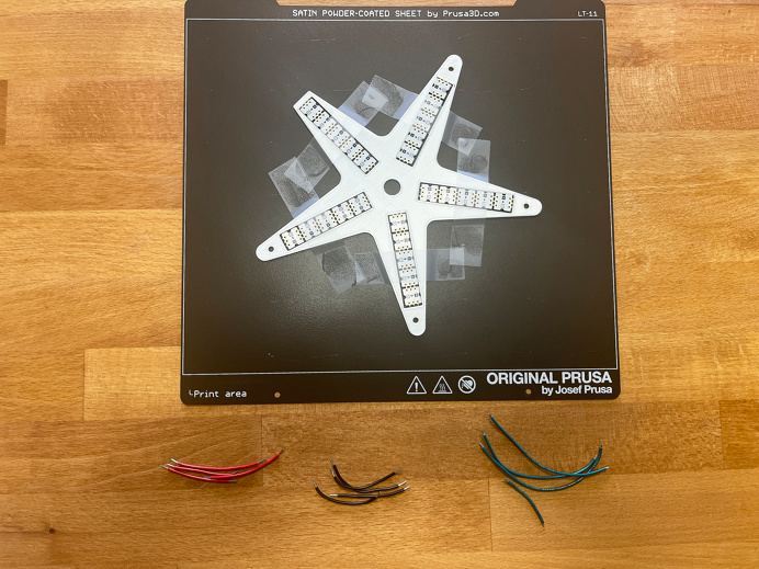
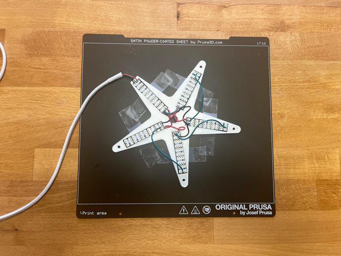
The PCB holder is printed separately and serves as a soldering aid. For this purpose, we leave it directly on the printing plate after printing. Bonus: Because plate is made of metal, it will absorb some heat so that we don’t damage the LEDs when soldering.

We leave the soldering aid on the print bed and use the metal to absorb the soldering temperature.

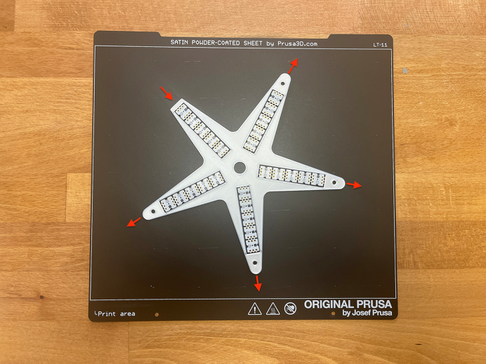
The LED strips have directional indicator arrows on the back that show how the signal is shifted by the LEDs. On the shorter arm, we insert the strip so that the arrows point inward; on the other four, the arrows point outward.

Pay attention: The arrows indicate how the LED strips must be aligned.

Then we fix the whole thing with adhesive tape and assemble a few cables. In our example setup, we use red for VDD, black for GND, and green for the signal.

Everything is fixed with adhesive tape; then it’s time to solder.

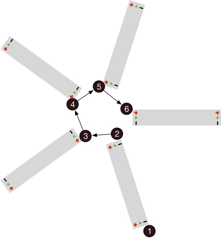
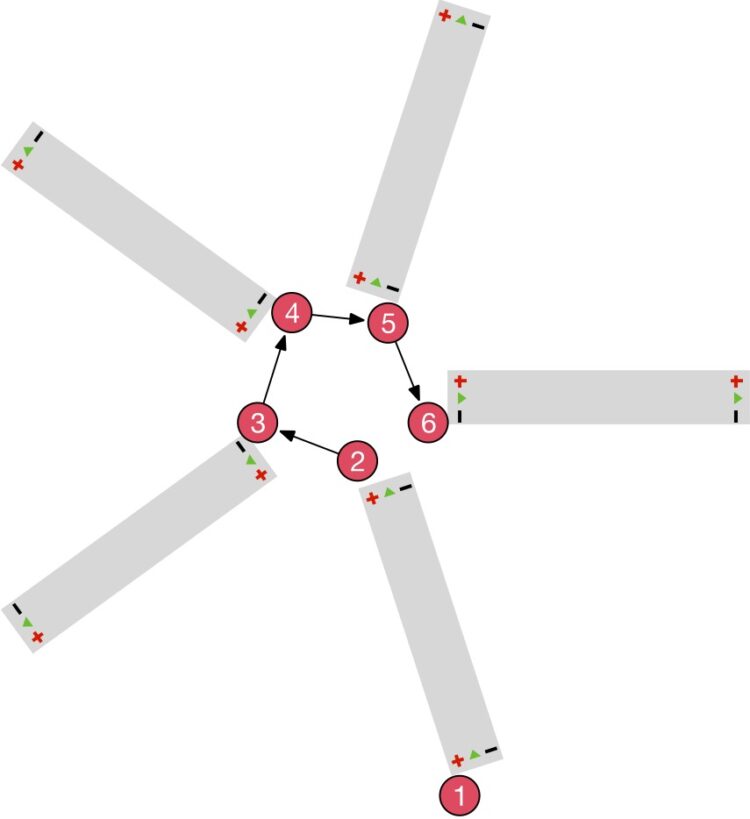
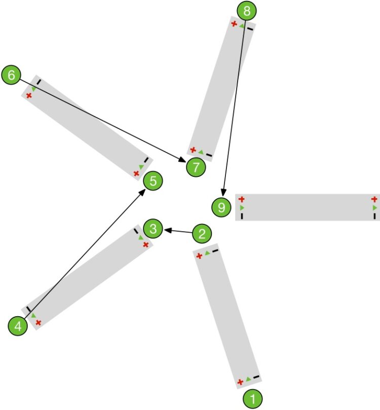
The diagrams show how to solder. Make sure the LEDs don’t get too hot. To ensure that the circuit board only comes into contact with the heat for as short a time as possible, it is worth tinning all the wires beforehand. We also place a small soldering point on the circuit board, but switch to the next board after each point so that the electronics are never exposed to heat for too long.

First we solder the ground pins.
Then we solder the VDD power supply pins.
Finally come the data pins. We use these cables to reconnect the LEDs to form a row.

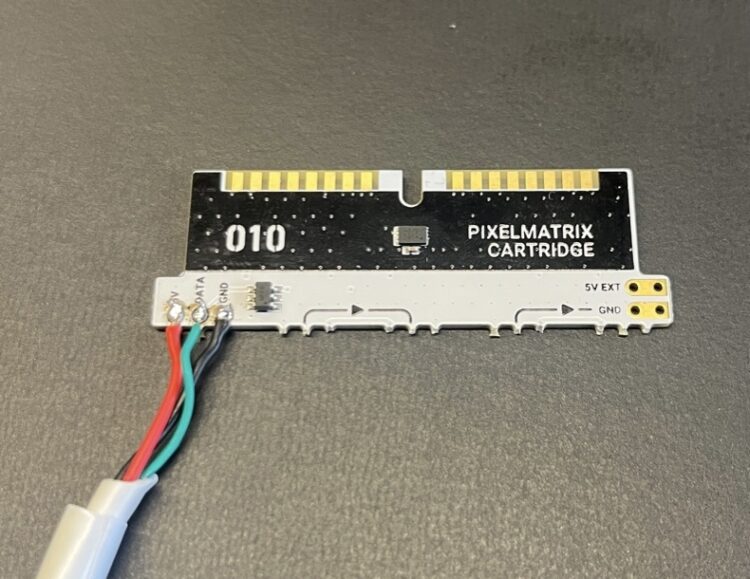
Now the board just needs to be connected to the cartridge. I used an old USB cable for this, as its plug was defective. These usually contain four wires, three of which we need for our star. 

We connect GND / VDD / DATA pins on the short arm of the star with their counterparts on the cartridge. 

An old USB cable is reused as our cable to the LEDs.
We only use three of the USB cable’s four wires.

Assemble and test

Before we assemble the whole thing, we carry out a small function test. 

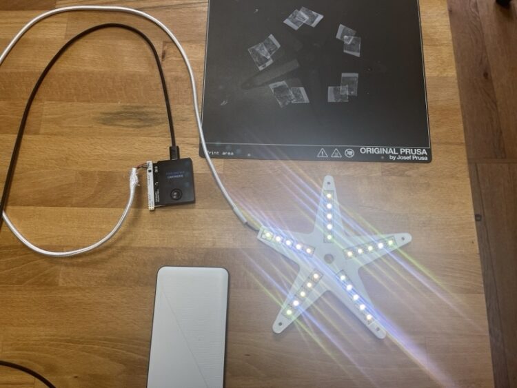
To do this, we connect the Oxocard Connect to a power bank and insert our modified Pixelmatrix cartridge into the slot. If all LEDs light up, we have done everything correctly. If one or more strips do not light up, pull the plug out again and check your solder connections. 

All LEDs light up to show that we have soldered everything correctly.

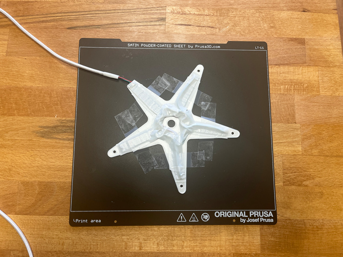
Now it’s time to assemble it. First, we tape the back with adhesive tape so that nothing slips later when we place it in the housing.

Before assembling, we tape the back of the LED strips with insulating tape.

Then carefully detach the inner part from the pressure plate and insert it into the underside of the housing.

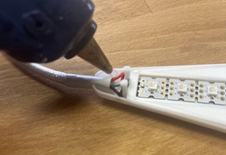
We fix the supply cable to the housing with a little hot glue. This creates a small strain relief to protect the solder joint.

A few drops of hot glue fix the cable in place.

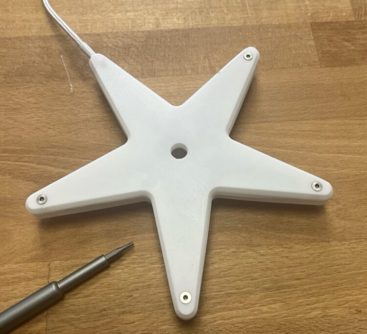
Finally, we put on the upper part of the housing and screw (or glue) the two parts together. Make sure the two parts of the eyelet on the cable engage properly before tightening everything with the screws.

Screwed together – now it’s time to program.

The additional printable adapter can be used to attach your star to the top of a tree, for example. The star can also be attached to a wall or door with double-sided adhesive tape. And, of course, the star is suitable as a holiday table decoration.

Programming

The LEDs can be addressed individually and can display various animations. Here, less is often more. Simple flashing of all LEDs in different colors is quickly programmed, but is only likely to be of moderate interest to your more demanding family members.

So we’ll show you how to create two cool effects: Rainbow and glitter.

Rainbow Star

The rainbow uses the HSV color space. In this color coordinate system, the color is not mixed in the form of red, green, and blue tones. Instead, we select a base color that provides us with a color spectrum. We use two further parameters to influence the saturation/strength of the color and the brightness.

Basic color HSV color spectrum (value range: 0-255).

Our algorithm now works in such a way that we select a color for the first LED that is determined by a number between 0 and 255. The next LED is assigned a color slightly further to the right of the color spectrum, and so on. In the next pass, we shift the color number of the first LED by 1, and so on down the line, creating the effect of the rolling rainbow.

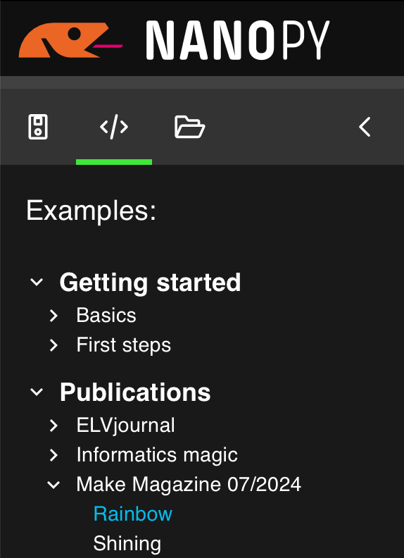
The script can be downloaded directly in the NanoPy IDE, under Examples / Publications / Make Magazine 07/2024.

Click on “Execute code” in the toolbar to start the program immediately. You can also load the script onto the cartridge (context menu “Load onto cartridge”), which will start it immediately when you insert it into the Oxocard.

The script contains two constants, for brightness (BRIGHTNESS) and speed (ANIMATION_DELAY), which can be changed using sliders. Clicking the button ends the animation.

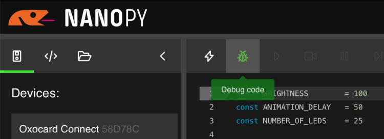
With the integrated debugger, the program can also be viewed during execution.

Explanation of the code:

In lines 1-2, we define two parameters with which we can influence the brightness and speed of the animations. This can be done directly in the code, or alternatively via the constant editor with the sliders on the right.

The LED library is initialized in lines 3-6. Here we define the switching pin, the number of LEDs, and the controller type. 

The actual program logic can be found in lines 12-19. Within the infinite loop, we iterate through the LEDs with a for loop. With each pass, a new base color is calculated from the HSV color space according to the formula j+(i*3).

Here you can see that we have two variables. Variable i contains the number of the current LED. This causes the color value between two LEDs to change by 3 each time. As j is increased by 1 with each cycle, the HUE value shifts and the whole thing is perceived as a flowing color spectrum. 

The color is then output on the current LED with setDigitalLed.

In line 18 we send the new color data to the LEDs, then we wait a few milliseconds until the loop starts again.

Block 20-25 checks whether the user has pressed a button. If this is the case, all LEDs are switched off and the program is then ended.

Glitter Star

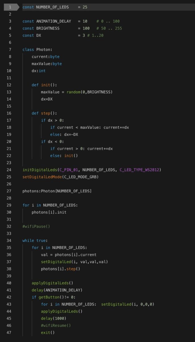
In the second example, the LEDs should shine with different brightness. To do this, we use an object (Photon class) for each LED. A photon has a certain brightness. The animation now looks like this: in each animation step, the brightness of the LED is increased to the defined maximum value and then reduced to zero again. We then define a new maximum brightness for the LED. If we do this for all 25 LEDs independently of each other, the result is an alternating effect that we can influence with the three constants BRIGHTNESS, ANIMATION_DELAY, and DX.

Explanation of the code:

The Photon class is declared in lines 7-22. We initialize a photon with init. First, we set a maximum brightness (variable maxValue).

In line 27, we define 25 photon objects. One object is assigned to each LED.

In the loop from line 34, we iterate through each LED again. With each pass, we read the current brightness value (photons[i].current) and write it to the LED buffer in line 37. 

Line 38 now calls the step() routine. If we go back to lines 16-22, we can see that we change the variable current with each call. This contains the current brightness. First we increase it to the maximum value and then reduce it again to 0. As soon as this state is reached, we initialize the photon object with a new maximum value.

Tips and tricks

It is worth trying out the finished examples first and experimenting with the constants. 

In the documentation under Cartridge / Pixelmatrix we find some background information on the use of LEDs, as well as further inspiration for our own developments.

Depending on the WiFi quality, the LEDs may flicker slightly. This can be avoided by switching off the WiFi communication during the animation. There are two commented-out lines in the scripts (Rainbow: lines 10 and 24, Shining: lines 32 and 46). If you delete the # character there, the animation runs more smoothly. However, you must then close the program first in order to reconnect to the editor.

Conclusion

You’re My Shining Star

This LED star is quick to build and a great eye-catcher. Using the same principle, many other beautiful decorative elements can be made to light up in an afternoon with the 3D printer. We look forward to seeing what you come up with!

Photos by Thomas Garaio