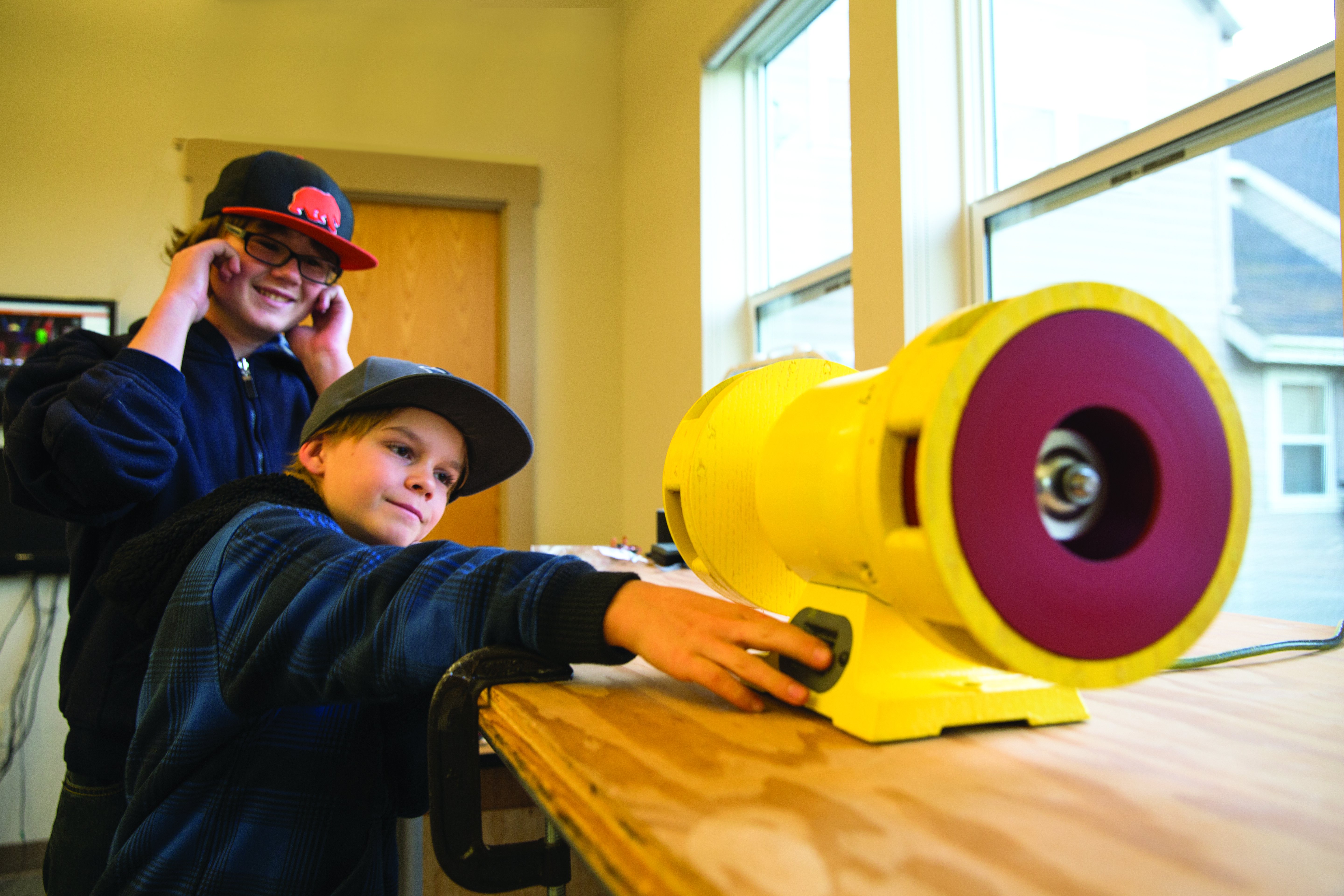
Air raid sirens have always fascinated me, especially the ones from World War II. The infamous wail indicated danger but also sounded the all-clear, inspiring both fear and relief. They’re also just awesomely loud. Nowaday there are electronic sirens, but most civil-defense sirens are still the mechanical kind — basically blowers designed to make as much noise as possible. I designed one that you can cut out on a CNC router and assemble in an afternoon!
Online I found a guy who’d made a DIY siren, but when I saw how much effort he had to put into cutting, balancing, and aligning all the fins and spacers on the rotor, I instantly thought of our ShopBot CNC router as an elegant solution — it could cut a perfectly balanced rotor every time. I just needed a motor.
Turns out that fractional horsepower AC motors cost $100 or more — so I decided to use the lab’s crummy old Harbor Freight bench grinder, because it actually looks like some old WWII sirens I’ve seen, and it costs only $45 brand new.
Now I could start on the CAD work. I started by measuring all the relevant points on the bench grinder with the wheel covers and grinding wheels removed: screw holes, shaft diameter, and washer thickness. I wanted to make the rotors (or “choppers”) easy to assemble, concentrically accurate, and capable of withstanding considerable centrifugal force. So I decided on sandwiching several layers of plywood, held together by wood glue and ¼” dowels. The dowels helped to line everything up accurately while also acting as a direct brace against the centrifugal load.
The stators were simple; I only had to make sure the rotor blades completely covered the openings in the stator. It’s traditional to use two simultaneous tones, in a 5:6 frequency ratio; so I went with 5 ports in one rotor and 6 in the other. I threw all the parts together in Autodesk Inventor — and to my delight it actually looked like a vintage WWII siren.
Next came the CNC cutting. Setting up the CAM was relatively simple: all the cuts were simple profiles, with a few partial-depth “pocketing” operations. The plywood had to be cut down to 24″×18″ to fit on our ShopBot Desktop (http://www.makershed.com/ShopBot_Desktop_Package_p/dssbdp.htm). I managed to fit all the parts for two rotor-stator assemblies on one sheet of ¼” plywood and two sheets of ¾”, and cutting went off without a hitch.
Assembly required patience and gentle persuasion with a rubber mallet. Testing the rotors was the scariest for me — I had no real idea if the thing was going to hold together or explode catastrophically under the centrifugal stress — but they spooled up to full speed and blew a surprising amount of air with almost no detectible vibrations. Sweet!
Next I mounted the stators, and discovered that the screw holes on the grinder were not concentric with the motor’s shaft, so there was some rubbing happening between the rotor and stators. I widened the screw holes on the stator so I could adjust for the misalignment, and sure enough I got the rotor to spin freely within the stator with only a 1/8″ gap between the two.
It was finally time to see if this thing was going to work. So again standing off to the side I switched on the motor. At first there was no noise at all as the motor slowly picked up speed. All of a sudden a faint wail began to emanate from the device, which quickly got louder and louder as the motor continued to pick up speed. By the time the motor got up to full speed the siren sounded so real and loud I had half a mind to duck and cover under my desk — it works!


