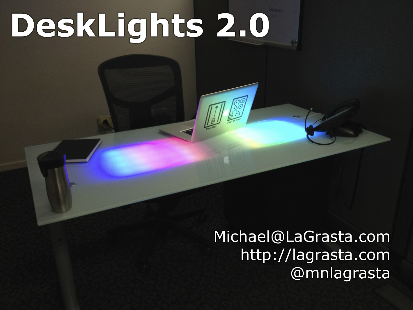
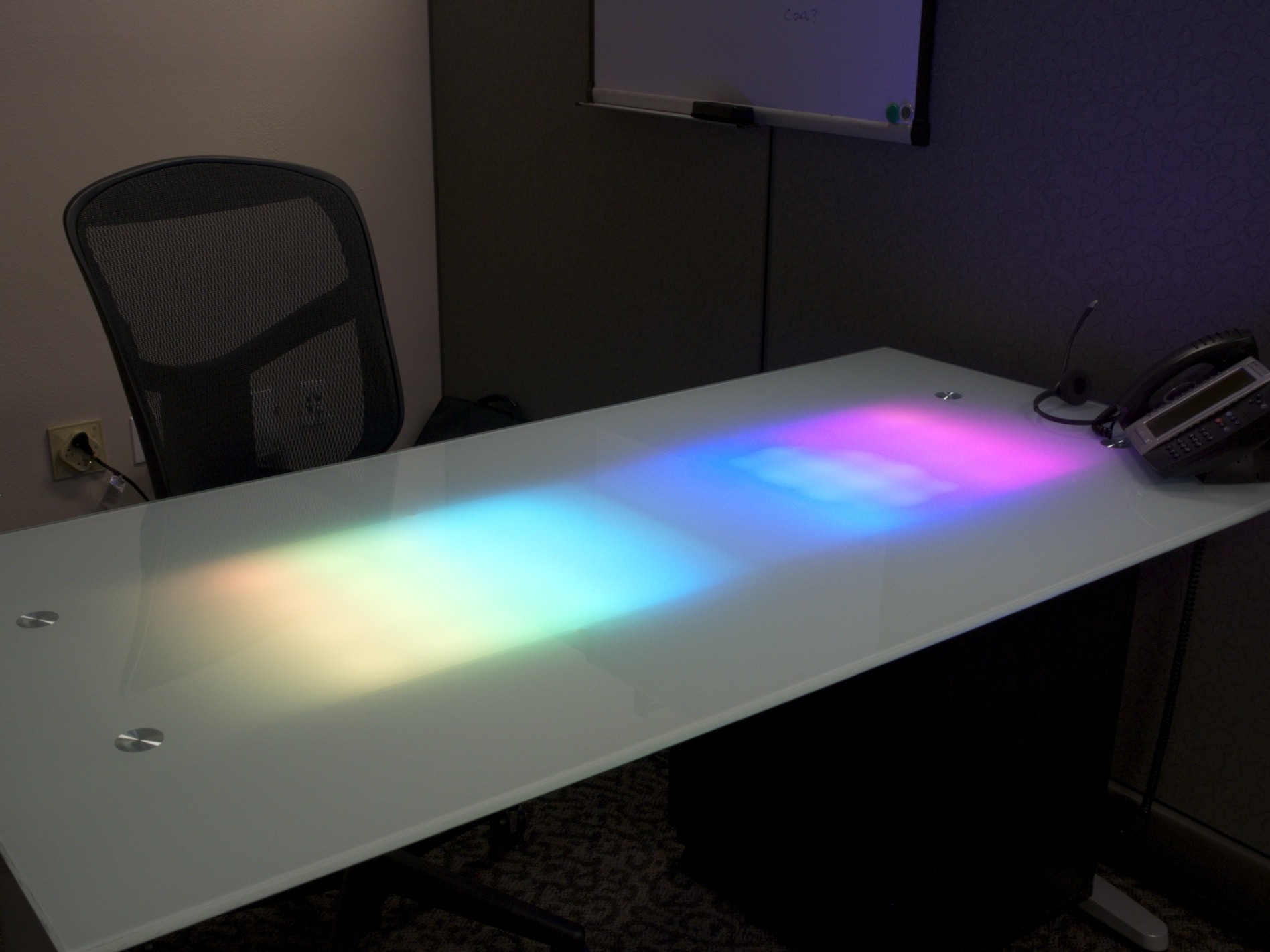
The desk receives event notifications over the network and alters its color and pattern to provide those notifications to the user. The combination of color and location can be used to communicate a wide variety of information.

Simple flashes of different colors inform me of new e-mail, phone, or chat messages. It is also possible to designate individual lights for certain purposes. A light can change from green to red to indicate server health and process load or increase its intensity the longer you ignore your email.

The desk can also run a default pattern between notifications. So far I’ve got the rainbow pattern, a robot sweep, randomly colored pixels, and a test pattern.

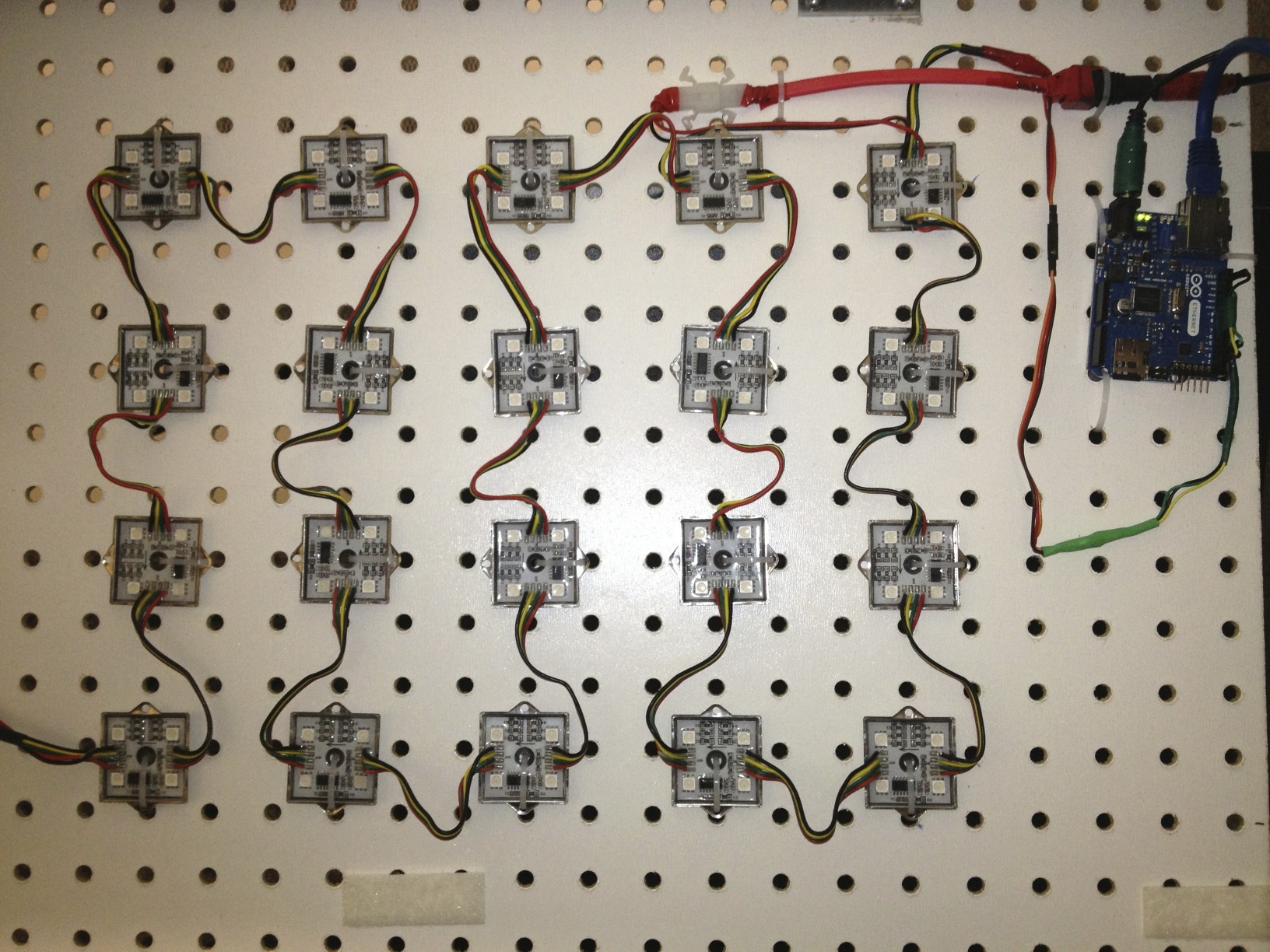
Inside the desk are 40 LED modules that can be individually set to any RGB color. Each module has 4 LEDs, giving a total of 160 LEDs for the desk. An Arduino Uno Ethernet microcontroller listens for incoming HTTP connections and converts this stream into serial commands for the lights. Since the desk is actually a web server, it makes it very easy to send commands to the desk. Every scripting language on the planet can request a web page.

To complete this project, you’ll need some sort of frosted glass surface. Alternatively, I’ve been told that some vellum paper behind regular glass or plexi will also work, but I have not tried it myself. You’ll need to be able to download some source code and load it onto the Arduino. You’ll have to make some wire connections by either twisting, soldering, or crimping. Lastly, the lights will need to be attached to some form of support to keep them in place. If you can do those things, you can do this project.

What will the next generation of Make: look like? We’re inviting you to shape the future by investing in Make:. By becoming an investor, you help decide what’s next. The future of Make: is in your hands. Learn More.

Project Steps

To start, you’ll have to choose your desk, picture frame, box, or whatever you want to use. Take some measurements and decide how many lights you’d like to include.

I used an Ikea Galant desk, which just happened to have the perfect frosted surface to diffuse the lights. That is really the most important part of the project.

Assemble the desk according to the normal instructions. We can easily work with the completed desk from underneath.

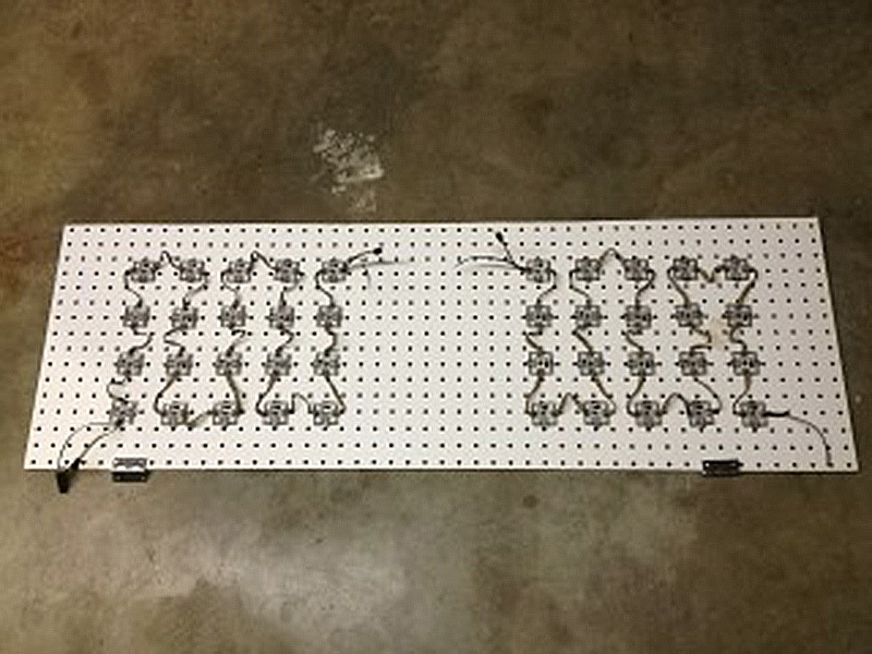
Now determine how you will support and attach the lights. In my case, the desk had a great open area between the two main support rails. So I cut a piece of peg board so that I could attach it from under the rails.

In my original version, I used foam core. I poked holes in the foam core and positioned the lights using twist ties. I then used painter’s tape to hang the board from the rails. This is a great way to play with the layout and allows you to easily change things around.

For this more-polished version, I used the peg board which saved me from trying to precisely drill 80 to 90 holes. The lights I used have a center hole and a mounting tab on two sides. I pushed a zip tie up through the center and down through one of the side holes. The two holes were enough to hold the lights in the desired orientation.

I also used double-sided padded tape to attach hinges to the light board. That, along with some velcro tape on the other edge, allowed me to repeatedly open up the desk to show visitors at my Maker Faire exhibit. This is totally optional, but if you want to make changes to the Arduino code, you’ll need to make sure you can access the USB or FTDI programming port.

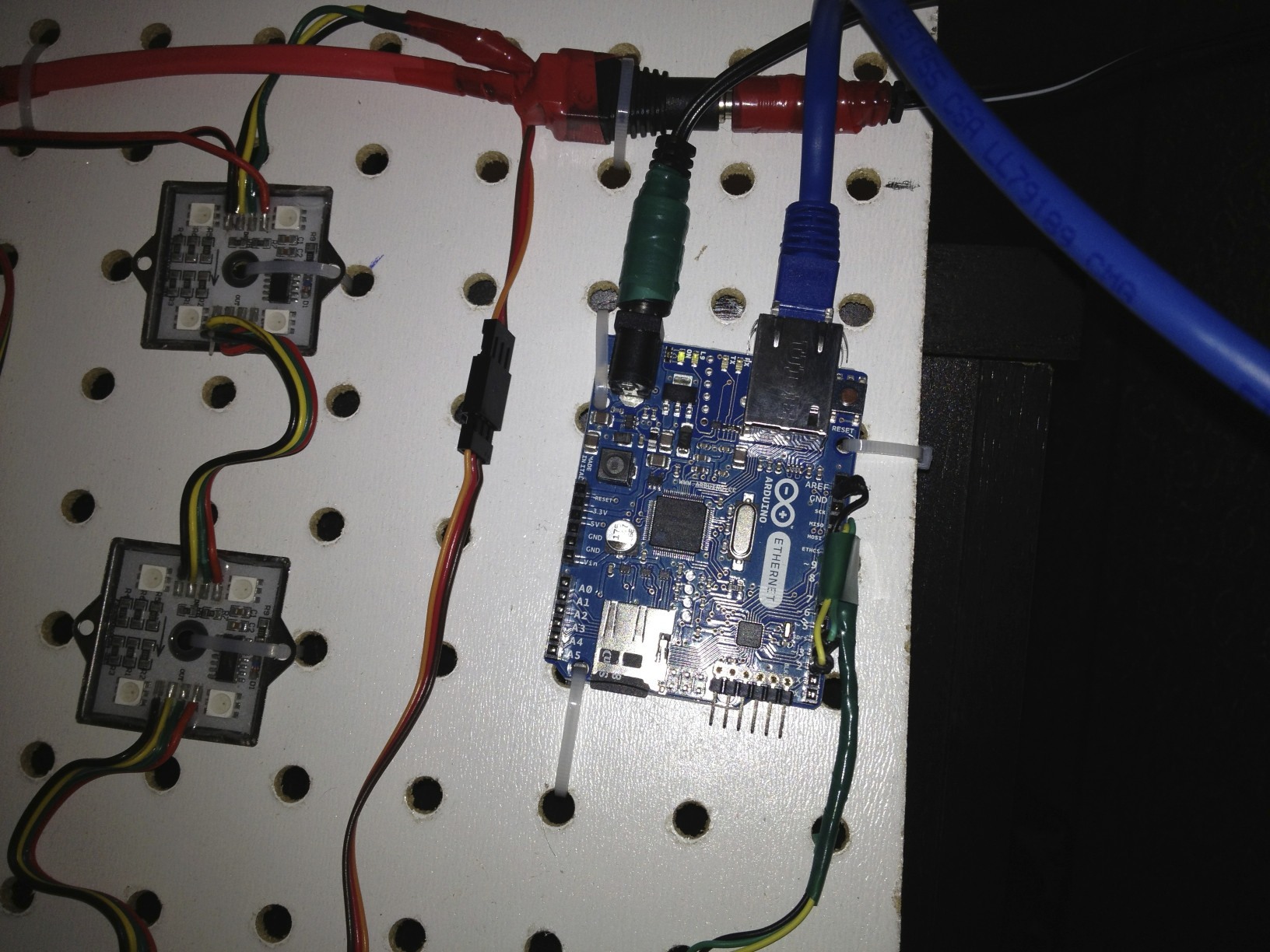
Now figure out where you want to place your Arduino controller. You’ll want to make sure you have easy access to connect the signal lines to the first light in the strand. The lights on this model are marked with an “In” and “Out” side, so make sure you follow that.

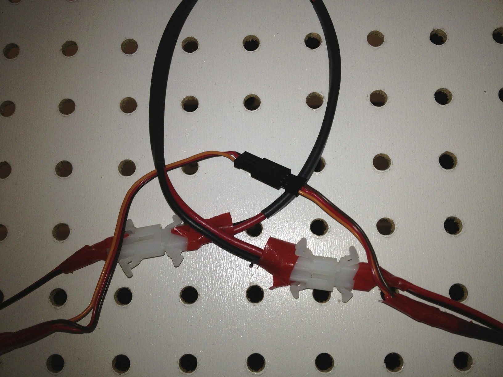
The Arduino will connect to the lights using the ground pin and two other pins. Pay attention to which pins you use because this will have to match the Arduino code. The default in the code is to connect the yellow Data wire to pin 2 and the green Clock wire to pin 3.

Once everything is placed, it is a good time to make your wire connections, by whatever means you prefer. I used RC servo connectors for the signal lines and Molex connectors for power. These were commonly available and easy to work with.

For the initial power connection to the lights I used a 2.1mm barrel connector with screw terminals. This matches the power supply in the parts list. CAUTION: Both the Arduino and light power supplies use the same connectors. If you connect the larger power supply to the Arduino, it will be damaged. I marked the two connectors with different color electrical tape to make sure I did not do this.

Now it’s time for the software. You can download the Arduino code from my GitHub account.

You’ll also need to download and install the Arduino tools to upload the code onto the microcontroller.

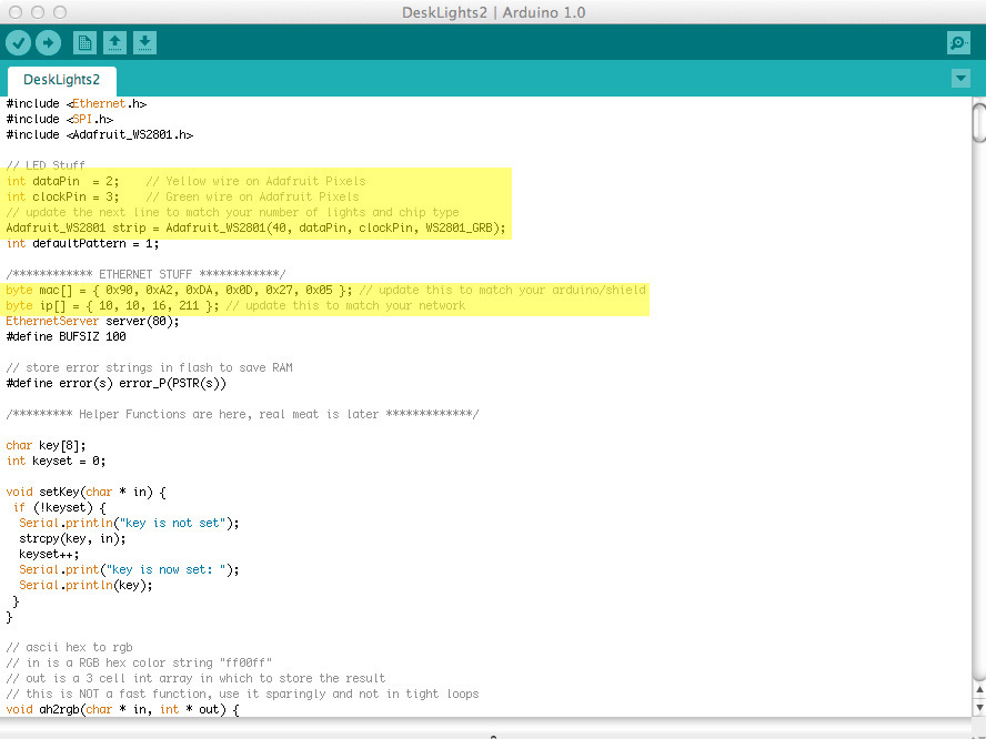
Open up the code in the Arduino software and modify the required lines. You’ll need to change things to correspond to your selected hardware. The entries are all marked in the code with the word “update” so search for that and follow the tips in the comments.

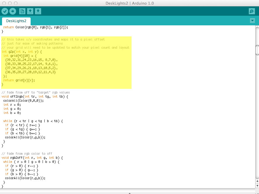
You’ll have to change the MAC address to match your Arduino Ethernet shield, the IP address to match your network, the number of lights to match your light strand, and the grid function to match your physical layout.

The grid function may be the trickiest. It takes an x.y coordinate and maps it to the numeric index of the light in the strand. Luckily, some experimentation makes it very obvious which lights are which.

Now double check your wiring and light it up. The code is set to run the test pattern immediately and then begin listening for incoming connections. If you don’t see the test pattern, then verify your power and signal connections. If that doesn’t help, make sure that the upload to the Arduino went correctly.

Now you can control the desk by requesting a web page. Just send it one of the accepted commands. You can find a list of commands in the code. The format will look like this: http://desk_ip/alert?ffffff or http://desk_ip/skype

Once you’ve confirmed that is working correctly, you can set up any scripts you want to send commands to the desk. I’ve included a couple of AppleScript files that can be used to trigger the lights from a Mac app like Mail. There is also a Growl style that shows how to get Growl to trigger the lights.

Remember that since you can control the desk over the network, these events can come from almost anywhere — servers, render farms, mobile devices, VOIP phones — whatever can request a web page.

Conclusion

Depending on how you like to make your connections, you may prefer different connectors or to solder connections.

Also, there are several variations of light strands. Any lights using the WS2801 or LPD8806 controller will work with the Arduino library used in this project.

On the first version of this project, I used foam core poster board and tape instead of the peg board and zip ties. That worked fine for almost a year until I decided to upgrade. If that is easier for you to work with, go for it.