Cheesemaker Yoav Perry writes:

When I began thinking about a sous vide machine that would not cost $400-$5000, I immediately began to understand the enormous potential it has to make a perfect cheese vat. At first, I did sous vide in the cheese vat and that’s where I met Lisa and Abe who inspired me to get a proper digital apparatus of controller and heater in there on the cheap and accurate. I then embarked on finding a form factor that can combine both uses: cheesemaking and sous vide.

See the original post on our blog.

What will the next generation of Make: look like? We’re inviting you to shape the future by investing in Make:. By becoming an investor, you help decide what’s next. The future of Make: is in your hands. Learn More.

Project Steps

Step 1

Disassemble the roaster – unscrew the bottom, remove insulation, and detach the thermostat. The wiring is very simple, but the roaster’s thermostat is difficult to remove.

Step 2

Prep four high-temperature wires. Two will be the power cords, so attach ring terminals on either end. The other two will control the relay, so attach spade terminals.

Check that the ring and spade terminals will fit into their PID locations before fastening them on.

Pull on the wire and attached electrodes to ensure that they will not come loose.

Step 3

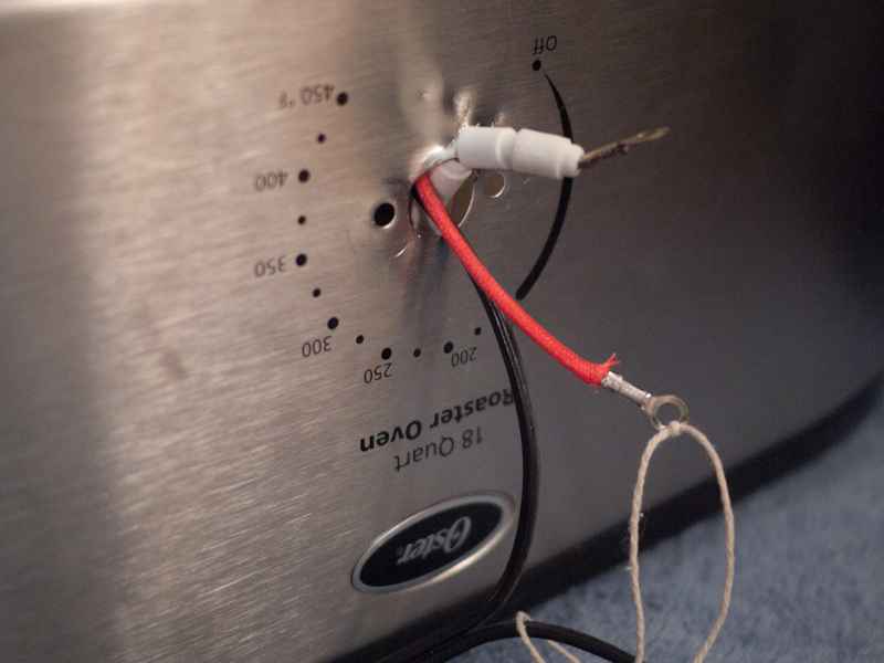
Next, we use heat-shrink tubing to protect wires. If tubing is not available, an easy substitution is to cover the thermostat hole in a few layers of electrical tape.

Step 4

Pull the two wires attached to the thermostat of the roaster out through the hole.

Attach the wires to the SSR according to the wiring diagram.

Step 5

Take one prepped wire with ring terminals and connect it to the roaster power wire inside the roaster.

Connect the other wire with ring terminals to SSR terminal 2.

Connect the other ends of these wires to the PID controller terminals 1 and 2.

It’s now time for the prepped wires with spade terminals. Use one wire to connect SSR terminal 4 to PID terminal 7, and the other to connect SSR terminal 3 to PID terminal 6.

Finally, connect the thermocouple to PID terminals 8-10 as shown in the wiring diagram.

Step 6

We have found the Pt-100 sensor to be particularly sensitive to water so we put the whole thing inside a latex glove.

Step 7

Lastly, we put the end of the air pump tubing into the air pump, and the other end between the tines of a fork to weigh the tube down.

Step 8

The last step is to correct the thermocouple settings on the PID controller. On the PID, hit SET, enter the number 0089, and press SET again. Scroll up or down so that ”Inty” is blinking, and press SET. Then scroll so that “Pt10.0″ is blinking. This lets the controller know we are using a Pt-100 and want to measure temperature to 0.1 degrees. Press SET, scroll to “End” and press SET.

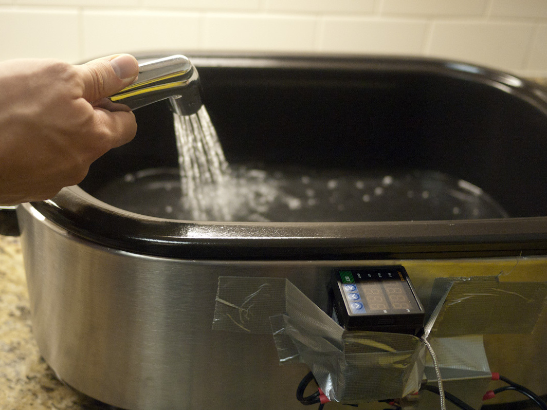
And she is finished! Add water to the tub and plug everything in.