fig 5 Pendulum copy
Photo by Phil Bowie

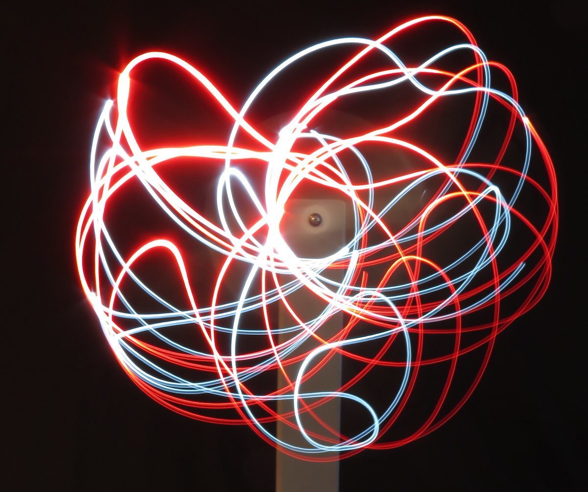
When Dr. Robert Reed, a Ph.D. at North Carolina State University, spotted the fascinating “Double Pendulum” project by William Gurstelle in a 5-year-old copy of Make: (Volume 22, April 2010), he asked us if we’d build two such pendulum rigs to help teach chaos theory to his students. He wanted the rigs to be portable for quick setup anywhere, with red and white LEDs (NC State colors) for creating arty, abstract time exposures.

[youtube https://youtu.be/tlh489Gkw7s]

We began by building a sturdy wooden stand (Figure A) capable of handling the sometimes-violent slinging forces generated by the crazily gyrating pendulum arms. We fastened the parts with wood glue and 2½” screws. The 2×4s at the bottom cross with a half-lap joint. We added four rubber feet for stability and painted the stand flat gray to minimize reflections during photography.

Fig-1-Pendulum_edit_4sophs
Figure A

Otherwise we pretty much followed Bill Gurstelle’s specs for the components. We used precision U.S.-sized bearings (¾” OD × ¼” ID × 9/32″ thick) so a U.S.-standard ¾” spade bit and assembly hardware would work. We super-glued them into acrylic arms, which we painted white for good visibility in motion. We added red stripes on the short arms to indicate placement of the LED pods. We also used standard ½” diameter plastic spacers, and chose ¼” thick foam for the Rott spacer.

Project Steps

BUILDING THE FRAME

Check out the diagrams below for instructions on how to put the frame together.

MAKING THE LED PODS

Figure B
Figure B

IMG_3561

The LED pods (Figure B) are our own invention, held in place by strong neodymium magnets. They automatically turn on when snapped onto the arm ends. The pods are self-contained in spring-steel strawberry hullers that look like clumsy tweezers but fit well on the pendulum arms, allowing fast, no-tool installation and removal. Strawberry huller designs vary in thickness, thus stiffness — so you may have to grind the sides of the bend somewhat to make it flexible enough to work.

Attaching pod to arm copy

Slide a scrap of ¼” plywood between the arms of the huller for backup while you center-punch and drill a 13/64″ hole in one arm, 3/8″ from the bent end, to accept the LED, and a clearance hole in the opposite arm for the machine screw. Clip off the top (–) lead of the disc battery. Insulate the long lead of the LED with heat-shrink tubing, then solder it to the bottom (+) tab of the battery. Super-glue a disc of thin insulating foam rubber inside the huller on the side opposite the LED hole. Maneuver the battery and LED into place and glue the battery (soldered-tab side) to the rubber insulator. Wrap the short LED lead around the machine screw and tighten the nut.

Finally, super-glue a neodymium magnet into the finger depression on the battery arm of the huller. Important: Magnets for both LED pods must have the same pole facing outward.

Using a flat-bottomed bit, drill a slight depression in each short pendulum arm, about 1¼” above the bearing’s center, to hold a disc magnet for positioning the LED pods. Your huller spacing may vary, so test-fit your pod before drilling.

Finally, super-glue one magnet into each pendulum arm. These magnets’ poles must be opposite of the magnets glued onto the LED pods. (They will attract each other through the battery.)

USE IT

When the pod is snapped in place on a pendulum arm, the magnets will hold it firmly and also complete the circuit to light the LED. For storage, slip a short length of surgical tubing over the huller’s battery-side jaw to keep the LED from draining the battery, which will last for up to 200 accumulated hours in many 10- to 20-minute time-exposure sessions.

Figure C
Figure C

After assembling at least 2 pendulum arms per Figure C, give the pendulum a shove and capture the action with a 5- to 10-second time exposure. Hard as you might try, no exposures will ever be the same.

And that’s the intriguing, often startling natural state of chaos.