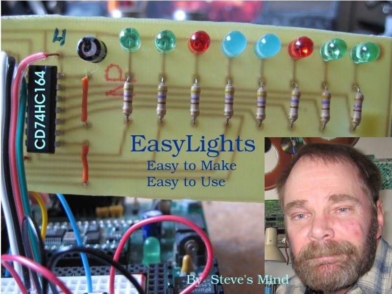
[raw]I was working on my Picaxe 28×2 robot from http://letsmakerobots.com/ and I wanted lights and I needed more sensors. I had four input pins left. With the 28×2 you can make the pins anything that you need. I went back to electronics to find some answers. I looked up shift registers on http://www.jameco.com/ and I bought the latest CD74HC164 serial-in parallel-out. This is why I made Easy Lights. For two pins you get eight lights. Yes, there is a little flicker. It is a shift register. Each time the lights change you have to shift in all eight lights. On slower systems you can use the Master Reset to clear the lights, but it still flickers when loading the lights.
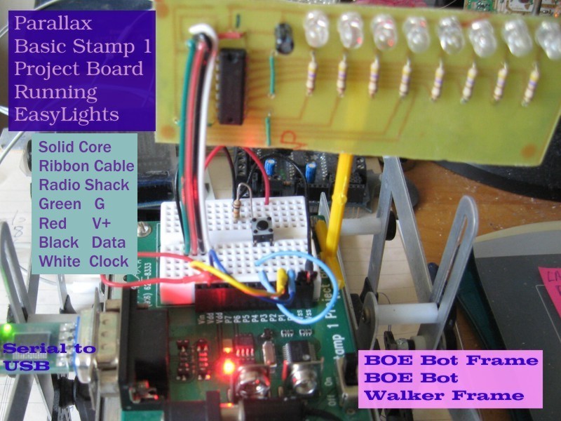
My programs are just a demonstration to show how my light board works. All you need is something like doLights or shiftout and maybe checkLights to run your lights. Programming can be fun. I left some mistakes in my Basic Stamp 1 program (EasyLights1.bs
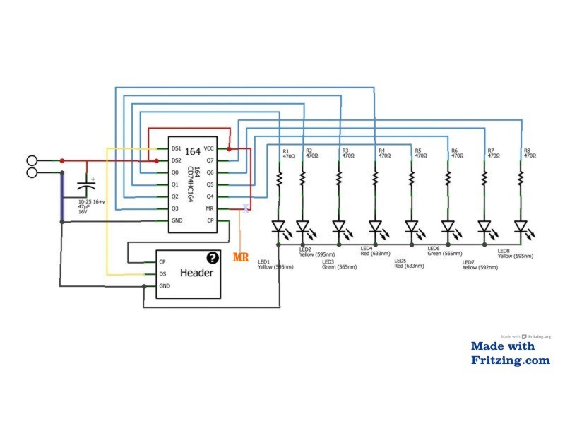
doLights is an example of programming for a device. A shift register like the CD74HC164 has three inputs (Clock, Data and Master Reset) that control the outputs, which are connected to lights in this case. You set Data to high or low and raise your Clock high, wait and set your Clock low and repeat this for all 8 bits in the register. To clear the lights you can load all 8 lights with Data low or bring Master Reset low, wait and set it high. Master Reset needs to be high for normal operation. Most processors like mine are too slow to necessitate waiting between setting the Clock high and then setting it low.
checkLights is my way of efficiently using the bits of each of my lights for easy logical testing. Bits only have two values: 0 for off and 1 for on. checkLights sets litTmp to the bit value of each light. This makes testing easy. If litTmp = 1 then doLitOn. Simple. Most processors give you access to the bits of the first few bytes of memory. If you tested bit 4 of the byte lights (light #5) you would get 16, the position value of that bit in the byte. Messy, to say the least. Logic operators like and and or will give you the bit position value too. In Larson to set the high bit of lights I set lights to 128 (the value of bit 7, the high bit in lights). Binary notation shows how the processor sees your numbers in binary.
- Position = value
- Bit 7=128
- Bit 6=64
- Bit 5=32
- Bit 4=16
- Bit 3=8
- Bit 2=4
- Bit 1=2
- Bit 0=1
- Examples:
- Bit 0 + Bit 1 = 3
- Bit 2 + bit 0 = 5
It is hard being a geek because no one ever understands you. I wish I had friends that I could share this with. I know how lost I can get in my projects. Geeks have hearts too and pretty normal lives.
Easy Lights would be a great project to teach electronics, programming, processors and making boards. If you are not making money on my ideas then have fun. If you make money then contact me, please.
For the files please see http://letsmakerobots.com and http://instructables.com as I complete this article.
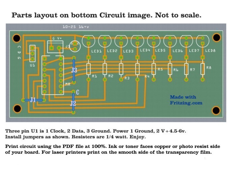
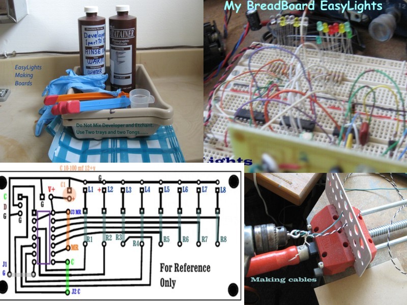
The PDF file contains the circuit board layout.


