YouTube player

Several years ago I watched a viral YouTube video that starred Jerry the Dachshund, whose engineer owner had built him his very own automated ball launcher. I had two dogs at the time, and was also unemployed with some time on my hands, so I decided to try my hand at building one.

After a few days rummaging through some junk boxes, I hacked together a slingshot-style automatic ball launcher that actually worked! It was pretty busy with parts though, and nearly 5 feet long. I wanted to go simpler.

Then on Discovery Channel’s Prototype This I saw a small spring mechanism that I just “knew” would work in larger form for my launcher. It was based on a gearmotor that rotated an offset peg on a wheel. The peg pushed a whacker rod around the wheel and against a spring, until it reached a point where the rod could spring back freely the other way, whacking the ball. I had to build it, and build it I did. Now you can too.

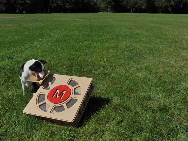
The Fetch-O-Matic ball launcher is the third and best version yet of this configuration. It will launch a tennis ball through the air about 25 feet with enough velocity to bounce and roll on for another 20–30 feet. It runs on 12–18 volts DC, so cordless drill batteries are an ideal rechargeable power source.

What will the next generation of Make: look like? We’re inviting you to shape the future by investing in Make:. By becoming an investor, you help decide what’s next. The future of Make: is in your hands. Learn More.

Project Steps

Cut the wood pieces.

Download and print the PDF templates at full size.

Cut the 1/2″ plywood as shown in wood_cutting_ guide.pdf. Start by cutting the length of the 4′ sheet and cutting out the two 20″ squares.

Mark points 1/4″ in from all 4 sides of the top and bottom panels, 2″, 6″, 10″, 14″, and 18″ from either edge. Drill a 1/8″ hole at each mark.

Decide on a top and bottom panel. Mark the center of the bottom piece and follow lower_motor_mount_template.pdf to mark the 3 surrounding holes. Or print the template, cut out the hole centers, and align and tape it over the board’s centerpoint, to mark the other 3 hole centers.

TIPS: With the hole saw and spade bits, drill only halfway through one side, then flip the board over and use the center hole as a guide to finish drilling from the other side. This makes for a cleaner hole with no splintering.

Drill as perpendicular to the surface as possible. For best results, use a drill guide block or a drill press.

Center-punch all 4 hole centers. Drill the large hole with a 1 3/4″ hole saw. Use a 7/16″ spade bit for the one behind it, and a 1/4″ bit for the others.

Following bottom_board_ template.pdf, mark 2 points 7″ and 9″ from the front, and 1 27/32″ from the left edge (just under 1 7/8″). Center-punch and drill with a 7/16″ bit.

Use a jigsaw to cut slots between the 7/16″ hole and the 1 3/4″ hole in the middle of the panel, and between the two 7/16″ holes near the left edge.

Follow top_board_template.pdf to prep the top panel. Start the 3″ square cutout by drilling a hole inside that the jigsaw blade can fit into.

For the right side panel, use a 1 1/2″ spade bit to drill a hole centered 5 1⁄2″ from one end. Drill only partway through, leaving 2 or 3 ply layers in place. Then drill all the way through with a 1/2″ bit.

In the back panel, drill a 1/4″ hole in the lower right corner, 3/4″ from the bottom and the right side.

Follow microswitch_ template_detail.pdf to drill 3 holes through the 1″×2″ micro switch mount block.

Trace the hopper pieces from hopper_template.pdf onto 1/4″ plywood. Cut them out and drill them with 1/8″ holes as shown.

Sand smooth the edges and openings on all the wood pieces.

Prep the motor and pulley.

Clamp the gearmotor in the vise and use a 1/4-20 tap to tap threads in the 3 mounting bosses of the gearbox.

The first motor I used needed approximately 1/8″ trimmed off each mounting boss. If your motor is different from the one shown here, you may need to cut less or more, or none at all.

The motor needs to sit flat against plywood with its shaft poking through a hole. If the bosses interfere, trim them down with a hacksaw.

File the cut faces even and flush with the ribs of the gearbox. File the flange near the motor housing flush to the same height. Then file the driveshaft to extend its flat about 1/4″ back toward the gearbox. Avoid filing the existing flat surface. Take your time, as this is a critical step.

Drill a 5/16″ hole through the pulley, halfway out from the middle and opposite the setscrew.

To make the peg, run a 5/16-18×1″ bolt through the hole from the side with the setscrew, and install 2 nuts tight on the other side.

Install the whacker.

Following whacker_arm_ template.pdf, cut and drill an 8 3/4″ length of 3/4″ square aluminum tubing with a 1/2″ hole completely through and a 1/4″ hole through just one side.

These holes must be perfectly perpendicular to the aluminum surface, or else the whacker will swing at a tilt and could hit parts inside the box. Use a drill guide or, even better yet, a drill press.

If your motor shaft is too long, add washers to the top of the motor bosses to lower the motor. The end of the motor shaft should be 1/4″ above the floor inside the box.

Screw a 1/4″ nut onto a 1/4-20×1″ bolt until it’s about 1/8″ from the head. Run the bolt through the 1/4″ hole in the tube, install a second nut inside, and tighten it down.

Attach the motor under the bottom panel by running three 1/4-20×1 1/4″ bolts with washers from the inside through the 1/4″ holes. Start at the back hole, screwing into the boss nearest the motor. Turn the bolt just a few turns before adding the others.

Touch 12V power to the motor until the shaft’s flat faces the slot in the bottom panel. Fit the pulley onto the shaft and run the 5/32″ Allen wrench through the slot to tighten the setscrew.

Insert the 1/2″ spacer into the middle of the pulley, then stack 3 or so washers around the spacer until they extend up just beyond the pulley’s rim.

Slide the whacker arm onto the spacer and secure it with the 6mm bolt running through a 6mm lock washer and a 1/4″ washer, tightened just snug for now.

Check that the whacker rotates easily around its full arc, hitting the pulley peg on both sides. Check that its midpoint is 1 3/8″ from the bottom panel, and the shaft bolt has at least 5/8″ clearance from the top panel, so the spring will clear it.

Once all the bolts are started, tighten them evenly a little at a time until they feel good and snug, but don’t crush the plywood.

Depending on your motor, you may need to use extra washers as spacers to get the spacing inside the box just right.

Remove the M6 bolt, apply Loctite to it, and reinstall. Remove and reinstall the setscrew with more Loctite. Wiggle the pulley as you wrench to ensure that the screw is centered on the flat. Wrench hard to get the set screw as tight as you can.

To supply power to the motor, connect negative to pin 2 (ground) and positive to pin 3 (low speed).

Assemble the hopper and case.

Join the 4 hopper pieces with masking tape, taping firmly along the inside edges. Use a square to align the assembly. Tape the wide end (the top) down onto a hard surface, and tape across the narrow end to reinforce it.

Dampen the 4 cloth strips, wring out, and lay flat. Apply an ample bead of wood glue down a corner joint of the hopper and smear it out about 1/2″ on each side. Apply a strip over each joint, smoothing and working out bubbles. Let dry overnight.

Install the ball guide and backstop as shown on bottom _board_template.pdf using wood glue and 3/4″ finish nails.

Starting with the left panel, join the 2 side panels to the bottom panel. Clamp each in place under the bottom, pilot-drill the holes, and install #6×1 1/2″ wood screws.

Join the front and back panels to the bottom in the same manner. Finally, join the sides to the front and back with one screw each, centered along the 2 3/4″ dimension.

Go back over all screws and check tightness. They should be flush with the wood surface. You can optionally countersink all the screw holes first.

Be sure to position the front panel to the left side, to allow the tennis ball to pop out on the right.

Sharp-eyed readers will notice that for this magazine cover, we built a left-handed version of the launcher, reversing the templates and switching the motor wires to achieve the opposite rotation.

Install the switches.

Cut the following pieces of hookup wire: 14″ red (2), 16″ red (1), and 28″ black (1). Strip 1/4″ of insulation from all ends, then twist the strands and tin with solder.

Solder or crimp 1/4″ female blade connectors onto one end of the 28″ black wire, and one end of a 14″ red wire. Solder the other end of this red wire to the micro switch’s normally open (NO) terminal. Solder the other 14″ red wire to the micro switch’s common terminal.

Trim the diode’s leads to 2″ and solder the cathode end (with the stripe) to one of the power switch terminals. Solder one end of the 16″ red wire to the other (anode) side of the diode, insulating with heat-shrink tubing.

Mount the power switch through the 1/2″ hole and 1 1/2″ indentation in the right side panel, with the On side of the switch pointing up.

Pilot-drill and screw the micro switch mounting block under the bottom panel alongside the ball guide hole. Angle the ball launcher upward, roll a tennis ball down the chute, and see where it hits the backstop.

Find a mounting position for the micro switch on its block, angled so that the ball pushes down the roller at the end of the lever. Adjust its position until the ball triggers it consistently, then mount it with two #4×3/4″ screws.

Route the micro switch’s common wire and the 28″ black wire through the 1⁄4″ hole near the power switch. Pull through a length of black wire equal to the length of the red. Route the rest of the black wire and the power switch’s 16″ red wire out the 1⁄4″ hole in the back panel.

Finally, solder the micro switch’s common wire to the other leg of the power switch.

Make sure the wires and switch are clear of the arc of the whacker. I used nylon cable guides and zip ties to tidy up the wires.

Install spring, hopper, and leg.

Install a 1″ bolt up through the hole in the top panel, with a nut on each side. Leave a gap between the bolt head and nut. With the whacker pointing forward, hook the spring between the bolt on the top panel and the bolt on the whacker.

Clamp the top panel in place and screw it to the side panels like you did with the bottom panel in Step 10, starting with the front right side.

Place the hopper over the hole in the top panel, with its short side toward the front of the box.

Drill four 3/32″ holes through the holes in the hopper and into the top panel, each at a 45° angle except for the right side, which should be drilled 90° straight down into the right panel. Install a #4×3/4″ screw in each, and tighten in turn just until contact is made with the hopper.

Test by lowering the top panel and positioning it on the box; it should pull on the spring.

Cut a 20″ length of 1 1/4″ wood dowel. Mark and drill centered 1/4″ holes in-line at these distances from one end: 3 1/2″, 5 1/2″, 7 1/2″, and 9 1/2″.

Mark a centerline down the front panel and 2 more lines offset 1 3/16″ on either side. Hold each pipe strap over the 2 outer lines, mark their hole locations, and drill with a 3/32″ bit. With everything straight and level, screw the straps in place using 1/2″ wood screws.

To prevent the dowel from rolling while you drill it, clamp it between 2 blocks of scrap wood.

The 1″ pipe straps fit the 1 1/4″ dowel; they’re actually bigger than 1″.

Slide the dowel through the straps with its holes facing out, and insert a 1/4″×1 1/4″ bolt in any hole below the brackets. The adjustable leg is now ready to support weight.

Power up and test-fire.

Turn the case over so the motor’s electrical connector faces you. Plug the red wire from the micro switch’s NO terminal onto pin 1, and plug the unconnected black wire onto pin 2.

From left to right, the motor’s first 3 pins are high speed (1), common (2), and low speed (3). To spin the motor clockwise, switch polarity on the battery.

Turn the power switch off! Connect its red wire to the battery’s positive side, and the black wire to negative.

Set up the Fetch-O-Matic in a flat area with about 40′ of space in front. Adjust the leg to a medium height. Make sure the power is still off, and check for foreign objects in the ball chute. Turn the power on, and check that the area directly in front of the launcher is free of dogs, kids, faces, etc.

Drop a tennis ball into the hopper. As it drops in and triggers the micro switch, the motor will turn and load the spring. When the whacker is pushed past the center point, it’s free to rotate and strike the ball, thus launching it!

Remember these safety precautions.

The velocity of the ball when launched isn’t fast enough to do much harm. Holding a hand in front of the unit during a launch will give you an idea of its speed. It doesn’t hurt, it just hits a bit hard. Catching one on the tip of the nose won’t make Rover happy, but chances are he’ll just shake it off and be a bit more cautious next time.

CAUTION: The launch arm inside the case will really hurt you if it strikes you during release! I got hit once in the finger and it felt like a hammer. It certainly has the potential to damage flesh, so observe these simple safety rules when using the Fetch-O-Matic:

Keep your hands out of the ball loading area and chute.

If the unit jams, disconnect the power and try to free it by jarring or shaking.

Do not reach inside if the spring is cocked. Remove the top and unhook the spring first.

Supervise animals and children.

That said, use caution and have fun with your Fetch-O-Matic automatic ball launcher!

Train your dogs to use the Fetch-O-Matic.

With a dog that likes to fetch, the trick is getting him to drop the ball into the hopper and not on the ground next to it. Try working with your dog’s favorite treats. Launch the ball and when Rover comes back with it, say “Hopper” and hold a treat over the hopper. Try to get him to drop the ball into the hopper in order to get the treat.

Repeat this until he gets it. Give him some attaboys and a few tosses from your own arm once in a while. Smile and laugh with your dog, who now loves you even more!

Visit http://dinofab.com/ball_launcher.html for video of earlier versions.

Conclusion

This project first appeared in MAKE Volume 31, page 98.