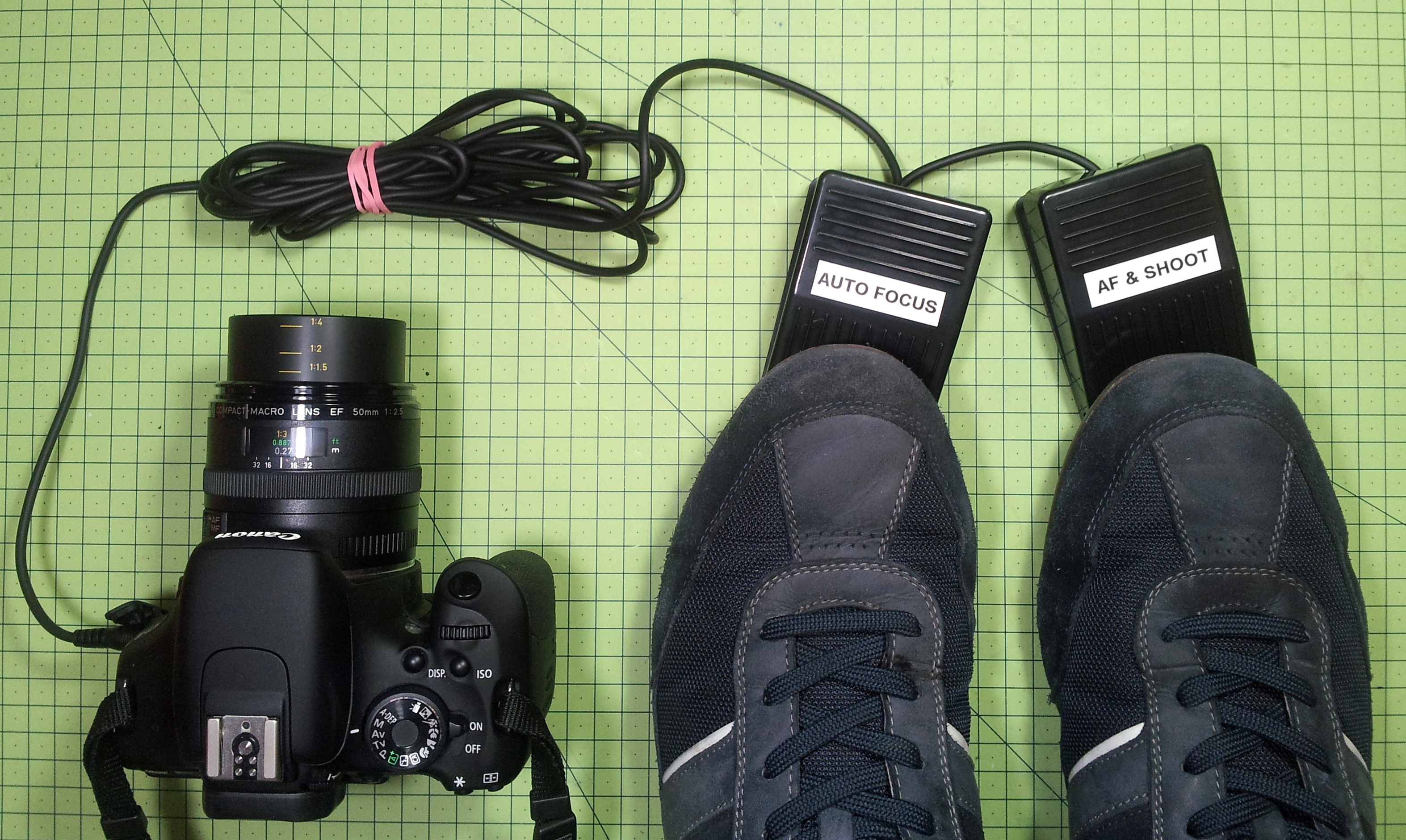
I enjoy creating step-by-step guides for my projects, but I’ve realized that in order to take pictures of hands-on work I need a hands-free way to operate the auto-focus/shutter on my DSLR Camera (Canon 600D).

YouTube player

I first tried using a hand-held remote – and pressing the button with my toes, and even trying to bite-to-shoot with my mouth! So as you might expect, necessity drove me to create these DSLR foot pedals.

Having shown this project to a few friends who take more professional photographs than myself, I realized that even if you are not photographing both your hands, using foot pedals just seems easier, as they are sturdy, reliable, and allow you to focus on the task at hand, rather than fumbling around for the remote.

Having taken apart my hand-held remote (and a few others since), they are often relatively simple switches, making them easy to adapt to other triggering mechanisms. You might start looking to use relays to create more elaborate/sensor-triggered projects after reading this!

Tools & Materials Overview
An overview of the tools and materials you will need for this project

What will the next generation of Make: look like? We’re inviting you to shape the future by investing in Make:. By becoming an investor, you help decide what’s next. The future of Make: is in your hands. Learn More.

Project Steps

How DSLR remotes work

A quick look at a typical hand-held remote shows you the 2.5mm jack. When using a multimeter, it becomes easy to figure out how this device works.

There are two switches which close sequentially: the first does ‘auto-focus’ and the second takes the picture.

Open the foot pedal

Unscrew the base of the USB foot pedal.

Using a flathead screwdriver, gently pry open the top part.

Unscrew the PCB, and remove it.

Modify the cable

Cut off one end of the cable, leaving the male plug on the longer part of the cable.

Next cut a short length around 25–30cm (this will be the bridging piece between your two pedals).

Strip sheathing.

Strip wires and twist strands.

The end result, with knots in each end.

Check the circuit

Use this wiring schematic and your multi-meter to check the circuit.

The metal contact closest to the grip is the ground. The following segment (when connected to the ground) fires the auto-focus. These are respectively labelled “C” and “W” in the above diagram.

Similarly, the final section, or tip, triggers the ‘shoot’ button (as well as the auto-focus just before).

The ‘double pedal’ design

Left Switch: Twist all pairs of colors together. Keep the Red pair out of the way. Connect the Ground and White onto the ‘ON’ terminals of the switch. This will be your Auto-Focus pedal.

Right Switch: Connect the Ground and Red to the ‘ON’ terminals. Keep the White out of the way. This will be your AF/Shoot pedal.

Connect to camera

Check that the circuit works, by connecting it to your camera.

When you are happy with the circuit, solder the wires to the switch, taking note that you’ll need to bend the wires to the right side where you mount them.

TIP: If you have not done so, you might also want to bind the loose wires with some insulation tape, as shown.

Test and adjust

Press the cable in the slot with a flat (not sharp) object.

Use a small amount of Super Glue to ‘tack’ the micro switch in place.

Re-assemble the pedal, and press down to check that the switch operates at a sensible height — you should hear a small click.

If you need to adjust the angle where the switch clicks, try gently bending the arm of the switch up slightly.

A good angle is shown which places the click in the middle of the press and does not requiring you to stamp on it to trigger the switch.

Make it sturdy

Now that you are happy with this, disassemble one last time and add significantly more glue to hold in place.

You could also add Sugru (optional) to give extra durability to the switches. Not only will it lock it in place, Sugru is also non-conductive at low voltages.

The ‘single pedal’ design (optional)

Although your fingers are highly sensitive and able to ‘half-press’ the auto-focus button, then press fully to shoot, your feet may not be so sensitive, so I recommend using two foot pedals. However, if you have the fancy footwork and dexterity, you can of course consolidate the circuit into one pedal, as shown.

In the diagram of the two micro-switch layouts, note that the ‘double’ switch has the switch-levers bent to different heights.

The third photo shows how to bend the levers, and also pinning the two switches together with pieces of cocktail-stick to maintain alignment.

Add labels (optional)

Now that you’ve reassembled for the last time, you will need some way to identify your pedals. I suggest sticky labels, but paint or correction fluid will also work fine.