This article appears in Make: Volume 80. Subscribe now for more great projects delivered to your mailbox.

In college at UC Santa Cruz in the late 1980s I started pointing a camcorder at my little Sony TV screen, creating video feedback — TVs within TVs within TVs, receding into the distance like an infinity mirror. As I zoomed the camera, all the tiny TV screens came forward, piling on top of each other. This is where things get interesting and emergent behavior occurs: Instead of seeing a bunch of screens you get colorful patterns and rotating shapes and general freakiness!

That little TV had the all-important hue / contrast / brightness / saturation knobs. Making good video feedback is a balancing act between the image getting too bright or too dark, the screen going all white or all black, going all blue or all red, etc. The knobs allow you to fine-tune the feedback and to keep it in the delicate middlespace where interesting things happen.

YouTube player

Around 2003 I decided to experiment with video feedback again, but I wanted more control over the image. I knew that the rotation of the camera and its distance to the screen are important, and that small changes in either make a big difference in the feedback that’s made. Instead of hand-holding the camera or putting it on a tripod like I did at school, I wanted a way to slowly and smoothly change its position and rotation.

My first prototype of the video feedback contraption in 2003. Credit: Dave Blair

I used a wooden dowel with a box on one end to hold a little Sony Mavica camera (with standard definition video output). On the other end was a thin piece of wood, like a yoke, for twisting the dowel. The dowel passed through a PVC tube and was heavily greased to smooth out the movement. Now the camera could move toward and away from the screen, and 360 degrees around its axis. This was a simple contraption, suspended from the low ceiling where I lived, but it produced some pretty cool results. Instead of wildly spinning colors like you might see in a 1970s Jimi Hendrix video, I was making tightly controlled, almost mandala-like patterns. But the knobs were at one end on the TV, and I was on the other end at the yoke. I could change the camera position and I could rotate the knobs, but I couldn’t do both at the same time.

What will the next generation of Make: look like? We’re inviting you to shape the future by investing in Make:. By becoming an investor, you help decide what’s next. The future of Make: is in your hands. Learn More.

Project Steps

Quest for HD

Starting around 2010 I had the idea to do video feedback in HD, but it just wasn’t feasible since affordable HD TVs don’t have those necessary analog knobs. Except for very expensive high-end monitors used in color grading, the controls for hue / contrast / brightness / saturation are usually all on-screen. Not only is it difficult to change these quickly, but when you do change them an indicator pops up, ruining the feedback.

When everyone began video conferencing in 2020, I hooked up my DSLR (with HD video out) as a webcam. At one point I aimed the camera at the monitor, and this got me thinking about HD feedback again. I went on an internet search for HD monitors that do have analog knobs.

What I found was a game-changer: Panasonic BT-LH900 9″ HD LCD field monitors. These little monitors are designed to be used at video production facilities or out in the field during video shoots. They probably cost a few thousand dollars new, but these were several years old and only cost a couple hundred dollars each on the aftermarket. And they had the knobs!

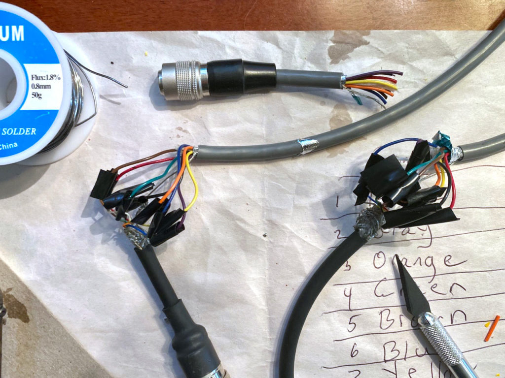
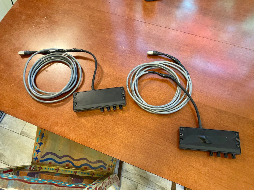
I figured I would desolder the potentiometers from the monitors, lengthen the wires, and bring them to the front of the contraption so I could move the camera and turn the knobs at the same time. But when they arrived, it turned out these monitors have a separate control panel with the knobs in it. This made it much easier to bring the knobs to the front. I just needed to find a cable with the right number of wires and splice in the connector that plugged into the back of the monitor. Perfect!

Teleprompter Glass

For this project I didn’t want to just make video feedback, I wanted to make actual fractals — infinitely complex geometric patterns that are “self-similar” at any scale, like the famous Mandelbrot set. I looked online and found a href=”https://sweetandfizzy.com/fractals/diagrams.html”>simple solution using a sheet of reflective glass at a 45-degree angle between two monitors. The camera looks at the upper monitor, but its output goes to the lower monitor too. It’s the mirror-image reflection of the lower monitor mixed in with the same image on the upper monitor that creates the fractals.

At first I tried a plain sheet of glass, but that didn’t work at all. I then tried using some tinting on the glass, but that cut out too much light.

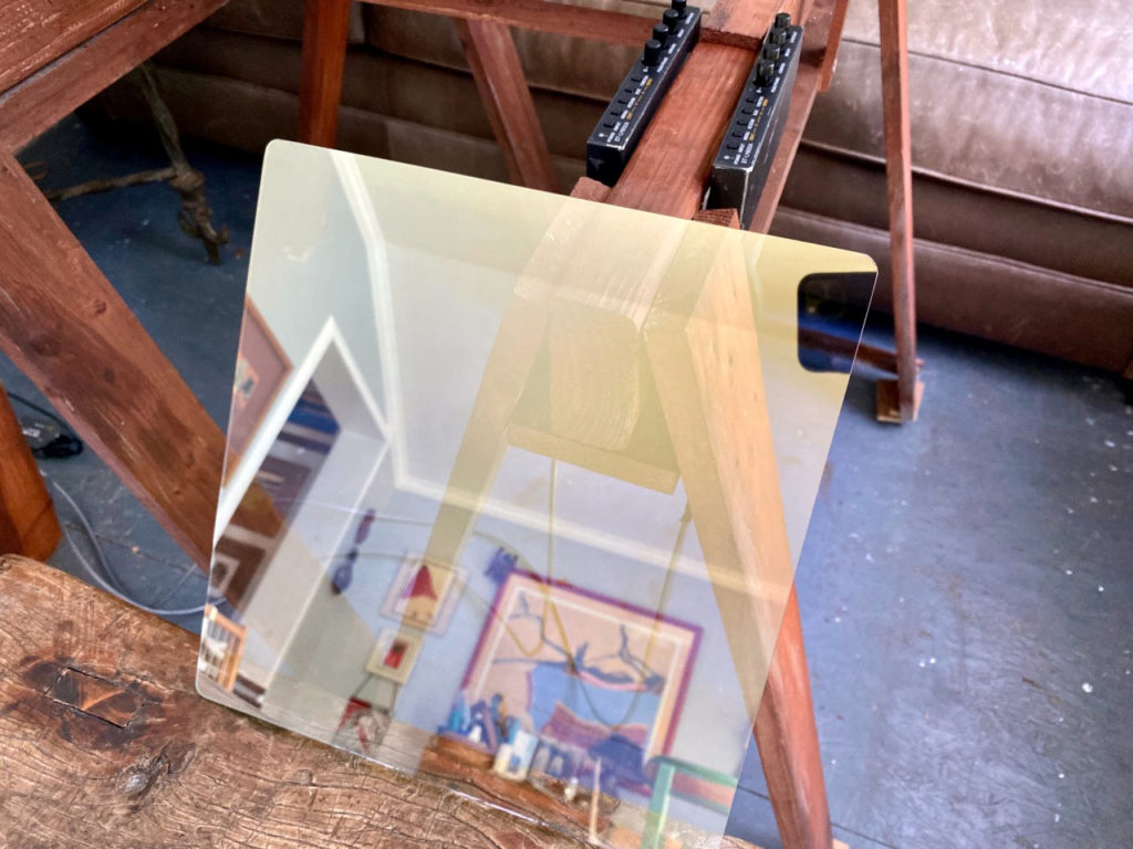
What ended up working great was teleprompter glass, sometimes called beam-splitter glass. Teleprompter glass allows a certain amount of light to pass through, and a certain amount to be reflected (often 60%/40%). I’m using 50/50 glass: 50% light transmission, 50% light reflection.

Field Guide to Field Monitors

There are a few tricky things about these little field monitors. They only take SDI input to a BNC connector — but the output of DSLR cameras is HDMI. Blackmagic Design makes the perfect thing for this: an HDMI to SDI converter for $60, with one HDMI input and two SDI outputs (one for each monitor, like I said, perfect!). I found that my Nikon D810 worked with this setup, but my Canon XC10 did not. That’s because these monitors need to see an interlaced signal, not a progressive one.

If you have trouble getting your camera to work with these monitors, you might need the more expensive Blackmagic Design Mini Converter UpDownCross HD — this little box converts from any video format to any other (and also adds a nice bit of delay, which can be interesting). Set DIP switches 1, 5, and 6 to “On” to create a 59.94 1080i output (I set the camera’s output to a frame rate of 59.94 for the smoothest image).

The monitors have menus that you should get to know. You might need to switch the input to Auto, or to turn off the on-screen display of information (you don’t want a little bar indicator coming up every time you adjust the knobs). Also, one of the knobs shares function between Peaking (a focus aid) and Phase (same as Hue). You’ll need to change this menu setting if it’s set to Peaking. There are a lot of other parameters you can play with, like sharpness.

Another tricky thing is that these monitors are usually powered either by a large, expensive, Anton/Bauer type battery, or by power from a camera through an XLR connector. I bought the power transformers my monitors needed (12V 2A), and found 2.1mm coax female to 4-pin XLR female cables from B&H Photo. This works great.

If you can’t find these specific monitors, there are a few other Panasonic options like the Panasonic BT-LH80W 7.9″, but they don’t have the knobs in a separate module, so you’ll have to carefully detach each of the potentiometers from the circuit board and lengthen the wires, then mount them in their own box.

Building the Rig

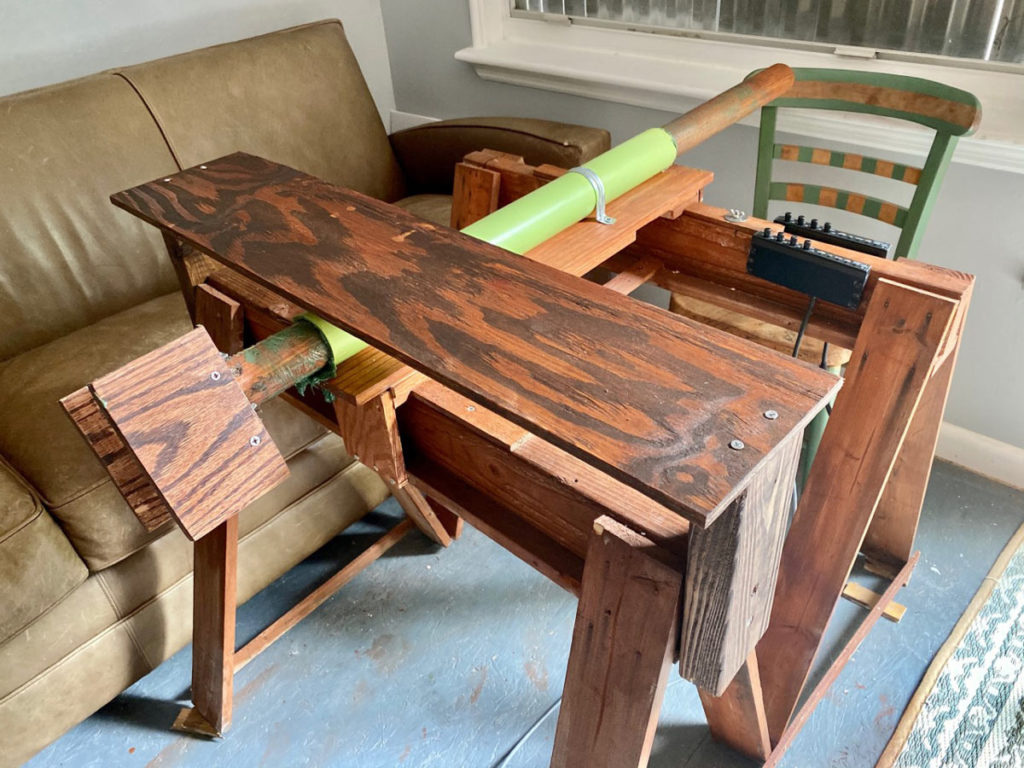
For the camera structure I used wooden sawhorses and mounted the PVC tube on a piece of wood on top of them.

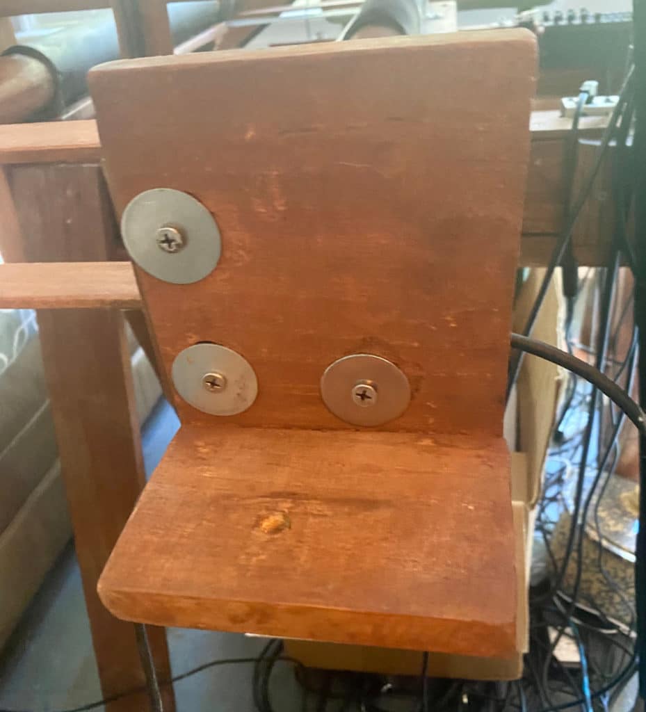
I built an L-shaped camera holder to mount the DSLR, using a standard tripod screw and washer. Make sure you can change your camera’s battery and get to its controls without having to remove it from the mount. If the camera is hanging over to one side because of this, you can use a weight on the other side to balance things out.

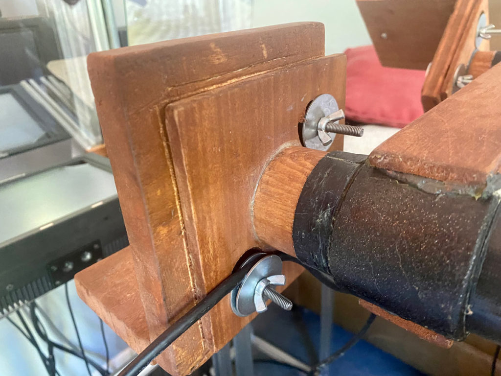
It’s important for the center of the lens to be aligned as perfectly as possible with the center of the dowel, so there’s no wobble when the camera is turned. I made a mounting plate on the dowel with oversized holes, and made matching holes in the back of the L-shaped camera holder.

Then I used large washers, long screws, and wing nuts to attach the camera holder to the mounting plate. These large holes allow for the camera to be slid around a bit and repositioned before securing it tightly.

It takes some experimenting to get the camera in the perfect position. A trick I discovered is to look at the lens in the refection of the teleprompter glass (make sure the glass is completely vertical), and rotate the camera. Pick a point in the reflection as reference, and you’ll be able to see if the lens is moving up and down or right and left as you rotate the camera. Adjust the position of the camera mount on the plate accordingly.

Once it’s perfect, lock the wing nuts down tight.

Building the Rig continued

I use heavy green marine grease on the dowel to allow for really smooth movements of the dowel through the tube (you’ll need to regrease occasionally). I also decided not to use a piece of wood as a yoke this time, but to just grab the end of the dowel instead. This seems to work best. Make sure everything is level so when the camera is moved back and forth through the tube it’s not going up and down.

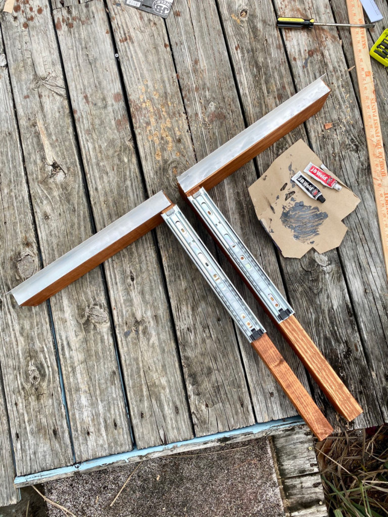
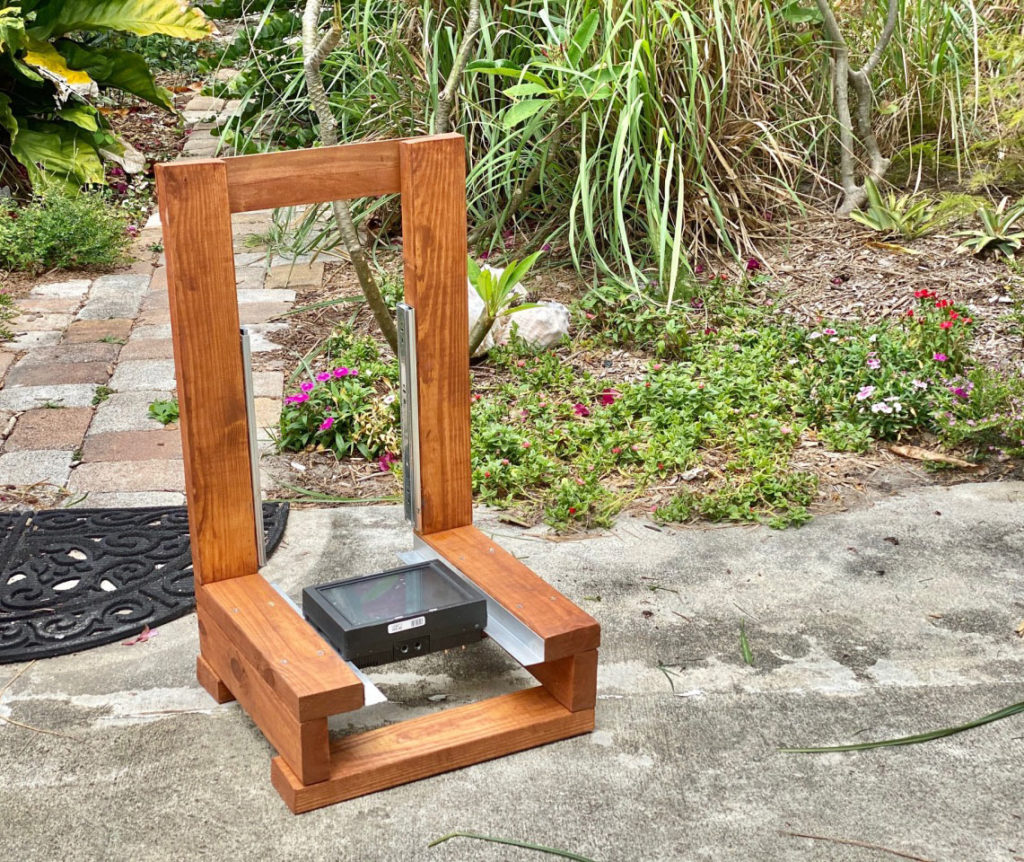
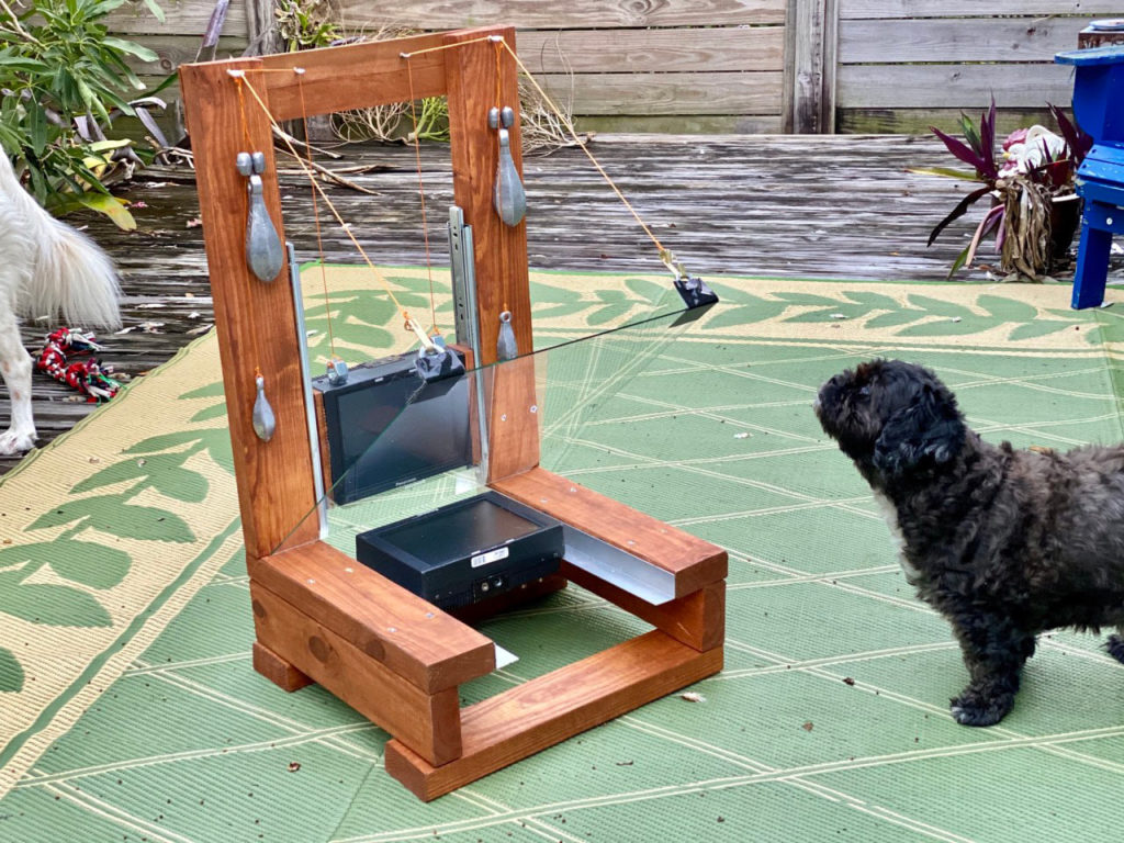
For the monitor structure I originally used wood, but later switched to T-slot aluminum. In both cases, I created a lower monitor platform where a monitor can slide back and forth on aluminum rails, and an upper monitor holder at a right angle to that where the monitor can slide up and down on tracks (the kind usually used for kitchen drawer slides). On the wooden structure everything is either screwed together or two-part epoxied. Instead of relying on precise measurements, I used the monitors when assembling this, kind of building around them, to ensure everything fit together properly.

I used 2×4s, but you might want to use something smaller. I first created two big L-shaped pieces by screwing two pieces of wood together at right angles. At the bottom part of these L-shapes I added another 2×4 across (this is what the structure rests on).

Next I glued on the outer drawer slide pieces and the lower rails.

Getting the right width for these lower rails is important — too wide and the lower monitor won’t fit between them correctly, too narrow and it will fall down between them. I then glued the inner part of the drawer slides to the sides of the monitor.

When everything dried, I slid the upper monitor into the structure as you would slide a drawer into place. I placed the second monitor to make sure the lower rails were the right distance apart, then took measurements so I could add the extra wood pieces to secure everything together.

For the upper monitor I used counterweights on string, much like a sash window uses. I did the same for the sheet of glass, so it can be moved and placed at any angle between the two monitors, although 45 degrees is usually where you’ll want it. I glued a couple of small pieces of wood extending out from the glass to attach these strings to. Finally, I used mounting tape to affix the two monitor control panels at the front of the device.

At first I was just looking over the top of the device at the upper monitor, but later I added a separate viewing monitor closer to me, resting on a piece of wood I added across one of the sawhorses. I recommend doing this, since it allows you to see what you’re doing in much greater detail. The easiest way to wire this is to use an HDMI splitter on the HDMI coming off the camera before it goes to the HDMI to SDI converter box.

Making Fractals

To create fractals, there are a lot of things to play with. I find I don’t mess around with the lower monitor’s knobs as much as the upper monitor’s (I ride the brightness on the upper monitor a lot).

Your DSLR will have different settings you can change. Increase the sharpness to create more stable images (but increasing it too much creates very line-y feedback). Play with the camera’s contrast and saturation. Take the camera out of auto iris and auto white balance — if it’s in auto iris the exposure will pulsate, and if it’s in auto white balance the color will pulsate. You can play with different ISO and f-stop combinations, focal lengths, and auto versus manual focus.

Changing the position of the upper and lower monitor in relation to one another will make different fractals. Rotating the lower monitor 90 or 180 degrees will create different fractals too (for 90° you’ll need to place something under the monitor to support it, since it will be off the rails).

Rotating the dowel smoothly and subtly can create very organic-looking feedback — things like sea creatures, plants swaying in the wind, etc. You can also create classic fractals, like the Sierpiński triangle.

It’s best to operate this in a dark room, although a bit of ambient light is OK. You’ll find very small movements of the knobs work best, and it might be difficult at first to create anything that looks good. Don’t give up — it took me many, many hours to start getting interesting results. Of course, hit Record on the camera when you do!

Feedback and Emergent Behavior

I learned about video feedback in high school when I read Douglas Hofstadter’s Gödel, Escher, Bach: An Eternal Golden Braid (this is a great book about all things recursive, I highly recommend reading it). Video feedback happens when you point a camera at a monitor that’s displaying what the camera sees — much like audio feedback happens when a microphone picks up what’s coming out of the speakers. In the monitor will be an image of the monitor (since the camera is looking at the monitor), and in that monitor will be an image of the monitor, and on and on and on. These images of monitors receding into the distance is kind of like when you’re in a dressing room with two mirrors facing each other and you see yourself over and over, trailing off into infinity.

Now imagine zooming the camera into the monitor, so the monitor in the monitor is getting bigger, and the monitor in that monitor is getting bigger, and all the monitors receding into the distance are now coming forward, piling on top of each other. This is where things start getting interesting and emergent behavior occurs. Instead of seeing a bunch of monitors getting smaller and smaller you get colorful patterns and rotating shapes and general interesting freakiness.

Ecosystems, biological systems, and social systems all operate on feedback loops, and they operate according to the inherent rules of that system (or laws of the Universe). With video feedback, these rules, or laws of the Universe, include the camera’s angle, distance from the monitor and the monitor’s control dial positions. It’s no wonder that the images created using video feedback are so organic looking. When people first see video feedback they often ask where the image is coming from. It comes from itself, and exists only because it exists. Something worth pondering.

Going Further

Since creating my original Video Feedback Kinetic Sculpture I’ve greatly increased the complexity of the device, adding more cameras and monitors so that two complete feedback rigs can now also feed back to each other.

I first added a second input to the monitors so I could take an image from my phone, for instance, to influence the feedback. I then wanted to give this second input some motion, so I added a second PVC tube and dowel, with a simple little monitor on the far end of the dowel. This second dowel rotates in unison with the main dowel by using a rubber belt (it also moves forward and backward with the main dowel – this was harder to figure out how to do).

A camera, placed next to the monitor structure, looked at this new monitor. The output of this camera was now the second input instead of the image straight from the phone – this gave motion to this image. I then added a little Roland switcher to be able to quickly switch what the main monitors see from this second input to the feedback loop, causing the second input image to “go into,” or kind of morph into feedback. I then replaced the simple monitor on the second dowel with another Panasonic BT-LH900 (and lengthened its control box cable to bring the control module up front). I could then do a separate feedback loop with the second camera and this monitor, and have that feedback influence the main feedback loop and fractal (and this second feedback could also morph into the main feedback using the switcher).

I then added a fourth Panasonic BT-LH900 on the other end of the second dowel and a third camera that looks at this monitor (this fourth monitor’s control module is also up front with the other three). I also added a second Roland switcher. Now, a third feedback loop can be created with the third camera and fourth monitor, and this feedback can be luma keyed over the second feedback loop (this creates a fractal of its own), and that new fractal can be used to influence the main fractal. This sounds pretty convoluted, but what it means is you can have one set of fractals made of another set of fractals!

The last iteration of the device (so far, that is) has two monitor structures next to each other (each with two Panasonic monitors and a sheet of teleprompter glass). To be able to fit two next to each other like this they had to be much smaller, so I made them out of T-Slot aluminum (if you haven’t worked with this, definitely check it out. It’s like working with a big erector set). The fractals made on the left monitor structure can be sent to the right structure to influence the fractals made on it, and the fractals on the right structure can be sent to the left structure to influence the fractals made on that. If they are both sending to each other at the same time, another feedback loop is created between the two structures, creating a whole new level of complexity (one that’s hard to even grasp, really). You can learn about my latest version, phase 3.5, at my website.

https://vimeo.com/daveblair?embedded=true&source=owner_name&owner=2240836

Conclusion

Next, I’d like to re-create all this in 4K. The intricacy of the fractals would be amazing! But just like HD wasn’t feasible in 2010, 4K monitors with the necessary knobs are not affordable now. Maybe in 2030 — but I’m hoping before then! I’ve started a GoFundMe to help make this a reality.

Please check out theLightherder.com for feedback videos, more explanation, and a link to my complete build notes.