

 Whether it’s the “Fukushima plume” and giant monsters on your mind, or you’re pioneering thorium reactors in your backyard, the classic Civil Defense CDV-715 Geiger counter has a perfect retro-style case to house a modern, sensitive digital Geiger counter.
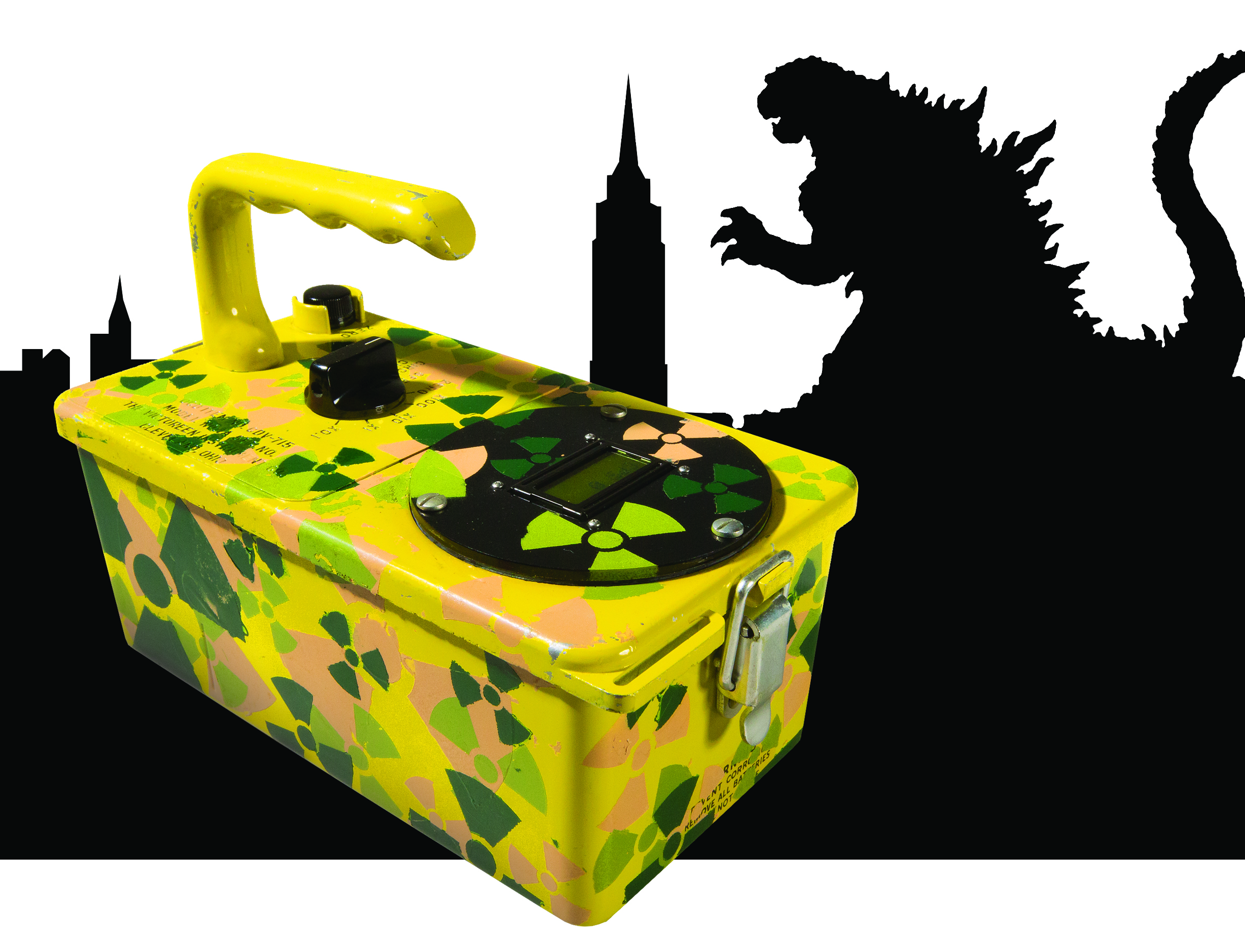
 In the 1960s, at the height of the Cold War, over half a million CDV-715 ion chamber radiological instruments were manufactured. In its day the CDV-715 could be found in government fallout shelters across the United States. When FEMA decommissioned the CDV-715, the instruments made their way onto the surplus market, where they’re available cheap. Unfortunately, this survey instrument only detects high levels of gamma radiation that would be encountered post-nuclear attack or incident, so it’s not sensitive enough for most radioactive detection work.
 You can easily fix that by swapping the counter’s old electronics for a new alpha-beta-gamma Geiger counter circuit and LCD Analog-Digital Meter. The top line displays Counts Per Second (CPS), alternating with Approximate Radiation Level in either Imperial measurements (mR/hr) or metric (mSv/hr). The bottom line is a power meter that provides a quick visual indication of the current CPS reading.
In Make: Volume 29, I showed how to build a Geiger counter circuit that easily fits this application. (Build it at makezine.com/projects/geiger-counter, then come back to this project for the retrofitting details.)

 I like this circuit because it lends itself to a number of GM tubes available on the market and can power any GM tube that requires either 400 or 500VDC. It’s also compatible with the Radiation Network (radiationnetwork.com), so you can share your readings with others worldwide — in the event of global radioactive lizard outbreaks.