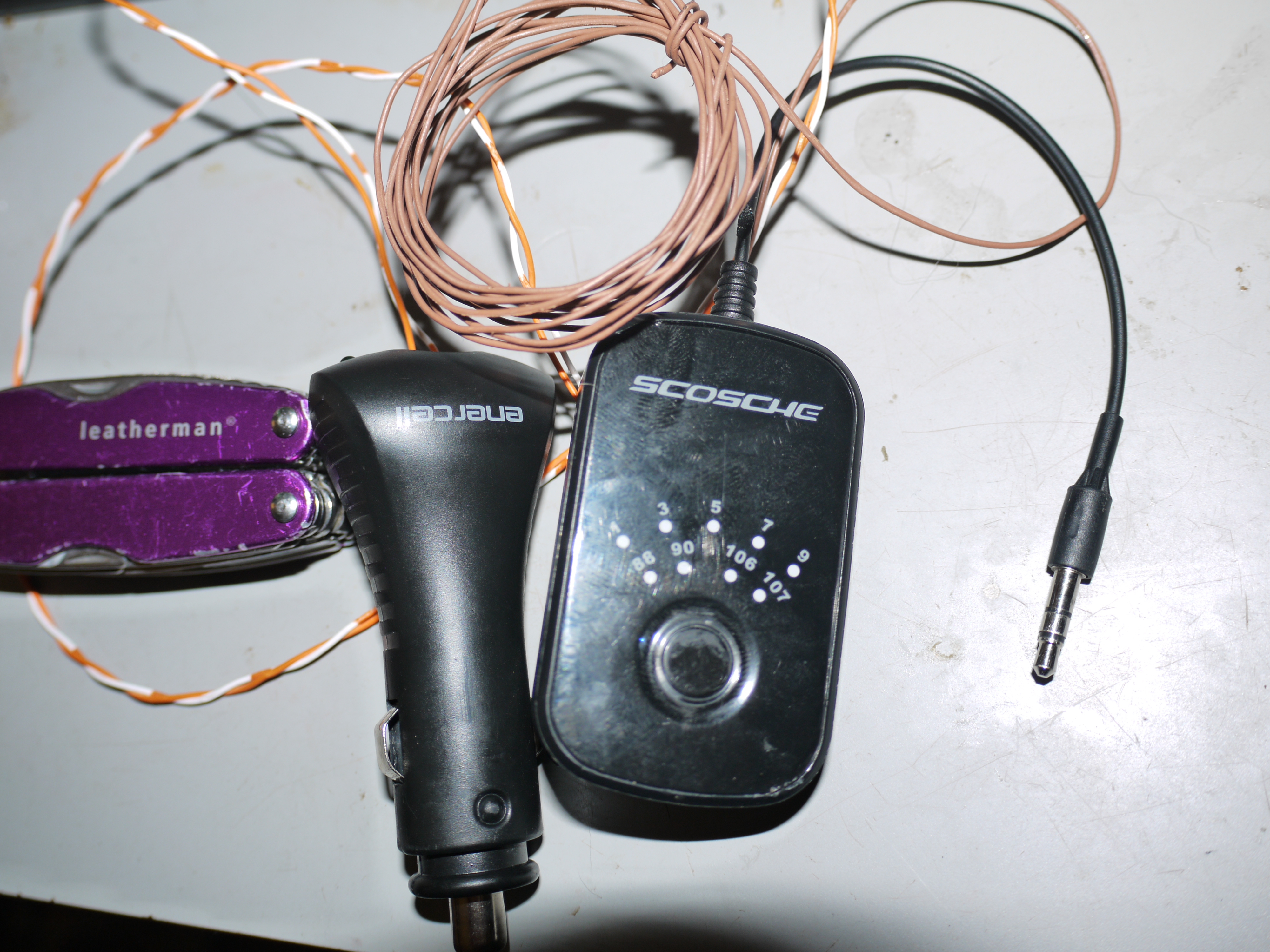
I suggest that anyone who is interested in this project do the V2.0 version instead. It is easier, safer for the PCB, and should yield practically the same results. The SWR is probably higher, but I can’t tell a difference in the field.
Do you want a cheap car FM transmitter with (unlike most of the products you can buy) great audio quality and great signal strength? You want to get yourself a Scosche FMT4 and hack it!
It is worth pointing out that someone who is willing to do this level of work could more easily change their car stereo for one with an AUX input, but my way is cooler and cheaper. :p
I am not someone who normally hacks stuff (as you’ll be able to tell when you see the soldering photos :P ), but I was annoyed by the lack of a decent cheap car FM transmitter. Annoyance is the mother of invention, apparently. :p
This is technically illegal in the US, but so is transporting dentures, so take it with a grain of salt, I guess.
My suggestion for avoiding legal issues would be this: “Don’t be a jerk”. Use an unoccupied frequency, and use the minimum power that you need to be happy. This can mean shortening the antenna (use a quarter-wave or an eighth-wave instead of a dipole), or (possibly; unconfirmed) lowering the input power.
A brief test led me to believe that transmit power increases as input power increases, but I’ve never seen a schematic of this thing (or a datasheet for the chip). At some point I will try to make time to check reception at various points with various input voltages to validate this theory. (Did you ever wish you had an oscilloscope?)


