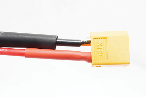
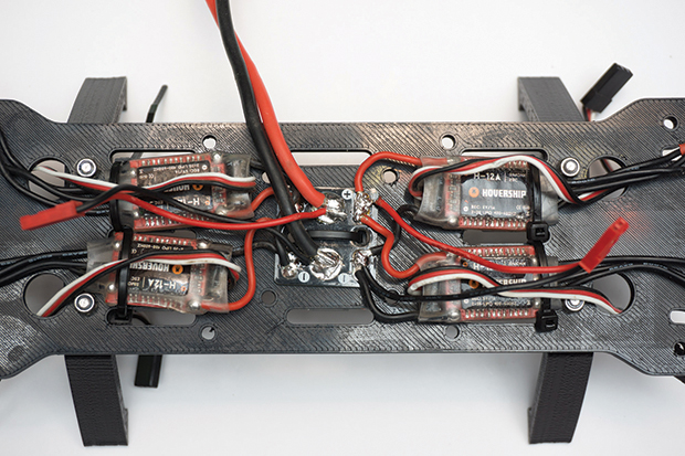
Solder the red and black 14AWG silicone wires to the primary power input pads of the power distribution board. Cut the primary power leads to about 130mm or longer. (The length will depend on where you attach the battery.) Cut 2 pieces of 6mm heat-shrink tubing and slide them down each power lead. Solder the power leads to their corresponding sides of the battery connector. Slide the tubing up to the battery connector and shrink them to cover the exposed solder connections.
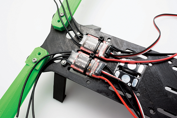
Solder the red (positive) wires from the electronic speed controller (ESC) to the corresponding pads of the power distribution board. Repeat for the black (negative) wires.
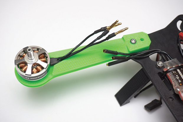
If your motors and ESCs did not come with connectors presoldered, it is recommended that you do so; this will make it easier to replace a component in the future, if necessary. Trim the motor or ESC wires to length, leaving some slack, and use a wire stripper to expose the wire inside. Solder the wire into the gold bullet connectors. Male connectors should be placed on the motors, female connectors on the ESCs. Cover each connector in 4mm heat-shrink tubing.
CAUTION: If your frame is made from
carbon fiber, which conducts electricity, any exposed connections touching the frame will cause shorts in the electronics.


